I’m having a strange issue and I’m not really sure where to continue troubleshooting and was hoping to see if anyone had any ideas. TLDR, SimpleFOC doesn’t work with the shield installed directly, but works with jumper wires.
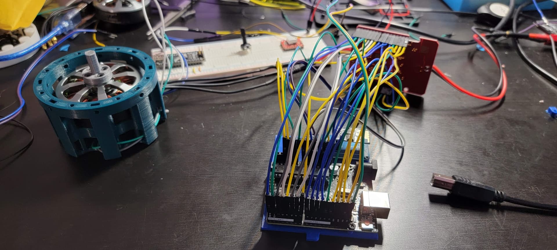
I’ve been running a Infineon BLDC-SHIELD_IFX007T to drive a Gartt ml5010 300kv motor. I have this paired with a AS5600 magnetic sensor.
Eventually after getting through several issues, I was able to get the full FOC example working on an Arduino nano and had started working on tuning. Now since the shield was meant for an Arduino Uno, I figured I’d scavenge an old board I had for an old project just so I didn’t have to deal with all the wires. However once installing the shield and uploading the same code to the Uno, upon startup, the motor just went haywire, and almost burnt out before I could disconnect it. I went back to the beginning and started with the open loop example and still it would not work.
Now wondering whether there was some issue with the other pins on the shield that was causing the problem, I removed the shield and went back to jumper wires to connect just the pins I had been using with the nano, and everything worked perfectly. So to try to find the issue I connected the rest of the pins one by one and retested and everything still worked properly even with all pins connected.
Just to make sure I wasn’t going crazy, I went back and installed the shield directly, and the issue came back. Removed it and connected every pin with jumpers and it worked once again. I’m sort of at a loss here as to why it would work with jumper wires as opposed directly installed. If anything I figured it would be the opposite with a better connection.
If anyone might have any ideas or suggestions it would be greatly appreciated
That does indeed sound like a very puzzling problem.
One thought that comes to mind is the following: I can’t find a pic of the bottom of the IFX007T board ATM, and I’m on holidays so I can’t pull mine out to check.
But is it conceivable that some part of the bottom of the IFX007T is in contact with some part of the UNO, in particular its USB port?
A short circuit via the case of the USB port would explain this behavior.
Oh wow, I didn’t even think about that. I’m still at work at the moment, but I’ll take a closer look when I get back in a few hours. I’ll post an update as soon as I find out.
So I’m back home and did a few tests. The USB port is definitely coming in contact with the pads, so I put a piece of electrical tape over it, ran a test and still have the same issue.
I tried to raise it a bit by not pushing the pins in all the way so there was clearance everywhere and the same issue is happening. The shield even ended up burning a bit…and I think my sensor somehow fried as well.
For reference, this setup is still working fine even after burning the board, except no position reading from my sensor. But it will run the open loop perfectly
There seems to be some other issue besides the USB port, but I’m kinda afraid to test more with power as the board burned just running the open loop example with the voltage limits set to 2 for a couple seconds.
I’m running an IFX007T and got it to work with an Uno just fine - but I couldn’t use it for my design due to the screwy serial port thing on the basic Uno. I now have it connected to a Teensy 4.0 and it works exceptionally well. I am running the board with peak currents of about 7.0 amps at the moment (24 VDC) to my BLDC motor. Yes the board does need a little heat sink, one thing that helped was lowering the PWM frequency to 12.5Khz instead of the default 25Khz - I suspect this reduces the switching losses a bit. I’m also using my own encoder on the motor and NOT using the hall inputs - at this point I’m just using the driver section of the board (10 wires between the Teensy and the IFX007T shield)
So I got a couple brand new IFX007T shields and a brand new Uno R3 on Friday, but I was out of town over the weekend. Finally had time to do some testing last night, and I was able to get everything running properly connected directly as a shield!
I’m going to do some more testing and troubleshooting over this week on the old board, but for now I’m going to chalk it up to some damage from either my modifications or burning it during earlier tests. As to why the old board still works connected through jumper wires but not directly is still a mystery to me for now.
With the new boards I started with no changes and just ran the open loop code with the shield connected. I did use the electrical tape over the USB port just in case, and it worked flawlessly.
Once that was done I had to do a few changes to make it work with my AS5600 magnetic encoder.
I changed the pins on SDA/ SCL (18, 19), the two grounds, 5v, 3.3v to stackable through pins to be able to attach my encoder. 18,19 aren’t used for anything on the IFX007T shield luckily. However pins A4 and A5 are used as their V_IS_RC (Filtered current sense voltage) and IS (Current sense pin of all three
channels). These pins interfere with the I2C connection and code would just get stuck when doing sensor.init() if these were connected, so I just chopped off the pins. I’m still not sure why it worked with these connected through jumper wires in my previous tests, but every time I plug the shield in directly, I couldn’t get I2C working.
Now with these changes, it seemed to be working flawlessly all last night.
@Chris_Duffey Did changing the PWM frequency lower heat generated? I did order some STM32 blackpill boards, but am waiting for them to arrive. Excited to see how much better the performance can be as opposed to the UNO. I got some bluepill boards, but I just could not get them to program correctly at all… guessing they were fakes.
Lowering the PWM frequency did noticeably lower the dissipated heat for me, incidentally the Teensy 4.0 @ 600MHz is running the SImpleFOC code as a servo loop in under 18 microseconds
18 microseconds… wow that is amazing… I may just have to pick a couple of them up just to play around with. Wish they weren’t so expensive per unit as I may need to use a bunch.
At the moment with my setup I can’t seem to go faster than around 35rad/s at 12v. I’m guessing it’s a mix of my cheap encoder and slow loop speeds. Trying to figure out the limits of each of my components, but waiting on parts is causing a lot of down time haha
Nucleo-64 boards will also go under 20 microseconds per loop if you are searching for a more convenient alternative.
I’ve been using Nucleo f411re and I highly recommend it.
Arduino UNO has a loop time of about 1ms and it will not be able to go much faster than 35 rad/s. I think the fastest that I was able to do was 60rad/s with an SPI encoder AS5047.