Hi everyone, I have a PCB with L6234D and AS5600 encoder.
I prove the magnetic i2c example, and I have good measuring’s, I try the open loop velocity and position and I have good results.
But when I try the closed loop my motor spins weird.
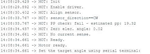
With the angle control example I have this results:
In the 14:08:33.767 → MOT: PP check: fail - estimated pp: 19.32 I have questions, because my motor has 12PP not 19, and why says “PP check :fail”
My motor only spins when I put in serial monitor near ranges, no when I put a more distance.
And the motor come back to one position but only in a near range, like a 1/2 PI.
PD: the motor model is: MN4006 KV380
The code:
#include <SimpleFOC.h>

// magnetic sensor instance - SPI
//MagneticSensorSPI sensor = MagneticSensorSPI(AS5147_SPI, 10);
// magnetic sensor instance - MagneticSensorI2C
MagneticSensorI2C sensor = MagneticSensorI2C(AS5600_I2C);
// magnetic sensor instance - analog output
// MagneticSensorAnalog sensor = MagneticSensorAnalog(A1, 14, 1020);

// BLDC motor & driver instance
BLDCMotor motor = BLDCMotor(12);
BLDCDriver3PWM driver = BLDCDriver3PWM(9, 10, 11, 8);
// Stepper motor & driver instance
//StepperMotor motor = StepperMotor(50);
//StepperDriver4PWM driver = StepperDriver4PWM(9, 5, 10, 6,  8);

// angle set point variable
float target_angle = 0;
// instantiate the commander
Commander command = Commander(Serial);
void doTarget(char* cmd) { command.scalar(&target_angle, cmd); }

void setup() {

  // use monitoring with serial
  Serial.begin(115200);
  // enable more verbose output for debugging
  // comment out if not needed
  SimpleFOCDebug::enable(&Serial);

  // initialise magnetic sensor hardware
  sensor.init();
  // link the motor to the sensor
  motor.linkSensor(&sensor);

  // driver config
  // power supply voltage [V]
  driver.voltage_power_supply = 7;
  driver.init();
  // link the motor and the driver
  motor.linkDriver(&driver);

  // choose FOC modulation (optional)
  motor.foc_modulation = FOCModulationType::SpaceVectorPWM;

  // set motion control loop to be used
  motor.controller = MotionControlType::angle;

  // contoller configuration
  // default parameters in defaults.h

  // velocity PI controller parameters
  motor.PID_velocity.P = 0.2f;
  motor.PID_velocity.I = 20;
  motor.PID_velocity.D = 0;
  // maximal voltage to be set to the motor
  motor.voltage_limit = 1;

  // velocity low pass filtering time constant
  // the lower the less filtered
  motor.LPF_velocity.Tf = 0.01f;

  // angle P controller
  motor.P_angle.P = 20;
  // maximal velocity of the position control
  motor.velocity_limit = 20;

  // comment out if not needed
  motor.useMonitoring(Serial);


  // initialize motor
  motor.init();
  // align sensor and start FOC
  motor.initFOC();

  // add target command T
  command.add('T', doTarget, "target angle");

  Serial.println(F("Motor ready."));
  Serial.println(F("Set the target angle using serial terminal:"));
  _delay(1000);
}


void loop() {

  // main FOC algorithm function
  // the faster you run this function the better
  // Arduino UNO loop  ~1kHz
  // Bluepill loop ~10kHz
  motor.loopFOC();

  // Motion control function
  // velocity, position or voltage (defined in motor.controller)
  // this function can be run at much lower frequency than loopFOC() function
  // You can also use motor.move() and set the motor.target in the code
  motor.move(target_angle);


  // function intended to be used with serial plotter to monitor motor variables
  // significantly slowing the execution down!!!!
  // motor.monitor();

  // user communication
  command.run();
}
I tried with this code
/**
 * Utility arduino sketch which finds pole pair number of the motor
 *
 * To run it just set the correct pin numbers for the BLDC driver and sensor CPR value and chip select pin.
 *
 * The program will rotate your motor a specific amount and check how much it moved, and by doing a simple calculation calculate your pole pair number.
 * The pole pair number will be outputted to the serial terminal.
 *
 * If the pole pair number is well estimated your motor will start to spin in voltage mode with 2V target.
 *
 * If the code calculates negative pole pair number please invert your motor connector.
 *
 * Try running this code several times to avoid statistical errors.
 * > But in general if your motor spins, you have a good pole pairs number.
 */
#include <SimpleFOC.h>

// BLDC motor instance
// its important to put pole pairs number as 1!!!
BLDCMotor motor = BLDCMotor(1);
BLDCDriver3PWM driver = BLDCDriver3PWM(9, 5, 6, 8);
// Stepper motor instance
// its important to put pole pairs number as 1!!!
//StepperMotor motor = StepperMotor(1);
//StepperDriver4PWM driver = StepperDriver4PWM(9, 5, 10, 6,  8);

// magnetic sensor instance - SPI
MagneticSensorSPI sensor = MagneticSensorSPI(10, 14, 0x3FFF);
// magnetic sensor instance - I2C
//MagneticSensorI2C sensor = MagneticSensorI2C(0x36, 12, 0X0C, 4);
// magnetic sensor instance - analog output
// MagneticSensorAnalog sensor = MagneticSensorAnalog(A1, 14, 1020);

void setup() {

  // use monitoring with serial
  Serial.begin(115200);
  // enable more verbose output for debugging
  // comment out if not needed
  SimpleFOCDebug::enable(&Serial);

  // initialise magnetic sensor hardware
  sensor.init();
  // link the motor to the sensor
  motor.linkSensor(&sensor);

  // power supply voltage
  // default 12V
  driver.voltage_power_supply = 12;
  driver.init();
  motor.linkDriver(&driver);

  // initialize motor hardware
  motor.init();

  // pole pairs calculation routine
  Serial.println("Pole pairs (PP) estimator");
  Serial.println("-\n");

  float pp_search_voltage = 4; // maximum power_supply_voltage/2
  float pp_search_angle = 6*_PI; // search electrical angle to turn

  // move motor to the electrical angle 0
  motor.controller = MotionControlType::angle_openloop;
  motor.voltage_limit=pp_search_voltage;
  motor.move(0);
  _delay(1000);
  // read the sensor angle
  sensor.update();
  float angle_begin = sensor.getAngle();
  _delay(50);

  // move the motor slowly to the electrical angle pp_search_angle
  float motor_angle = 0;
  while(motor_angle <= pp_search_angle){
    motor_angle += 0.01f;
    sensor.update(); // keep track of the overflow
    motor.move(motor_angle);
    _delay(1);
  }
  _delay(1000);
  // read the sensor value for 180
  sensor.update();
  float angle_end = sensor.getAngle();
  _delay(50);
  // turn off the motor
  motor.move(0);
  _delay(1000);

  // calculate the pole pair number
  int pp = round((pp_search_angle)/(angle_end-angle_begin));

  Serial.print(F("Estimated PP : "));
  Serial.println(pp);
  Serial.println(F("PP = Electrical angle / Encoder angle "));
  Serial.print(pp_search_angle*180/_PI);
  Serial.print(F("/"));
  Serial.print((angle_end-angle_begin)*180/_PI);
  Serial.print(F(" = "));
  Serial.println((pp_search_angle)/(angle_end-angle_begin));
  Serial.println();


  // a bit of monitoring the result
  if(pp <= 0 ){
    Serial.println(F("PP number cannot be negative"));
    Serial.println(F(" - Try changing the search_voltage value or motor/sensor configuration."));
    return;
  }else if(pp > 30){
    Serial.println(F("PP number very high, possible error."));
  }else{
    Serial.println(F("If PP is estimated well your motor should turn now!"));
    Serial.println(F(" - If it is not moving try to relaunch the program!"));
    Serial.println(F(" - You can also try to adjust the target voltage using serial terminal!"));
  }


  // set motion control loop to be used
  motor.controller = MotionControlType::torque;
  // set the pole pair number to the motor
  motor.pole_pairs = pp;
  //align sensor and start FOC
  motor.initFOC();
  _delay(1000);

  Serial.println(F("\n Motor ready."));
  Serial.println(F("Set the target voltage using serial terminal:"));
}

// uq voltage
float target_voltage = 2;

void loop() {

  // main FOC algorithm function
  // the faster you run this function the better
  // Arduino UNO loop  ~1kHz
  // Bluepill loop ~10kHz
  motor.loopFOC();

  // Motion control function
  // velocity, position or voltage (defined in motor.controller)
  // this function can be run at much lower frequency than loopFOC() function
  // You can also use motor.move() and set the motor.target in the code
  motor.move(target_voltage);

  // communicate with the user
  serialReceiveUserCommand();
}


// utility function enabling serial communication with the user to set the target values
// this function can be implemented in serialEvent function as well
void serialReceiveUserCommand() {

  // a string to hold incoming data
  static String received_chars;

  while (Serial.available()) {
    // get the new byte:
    char inChar = (char)Serial.read();
    // add it to the string buffer:
    received_chars += inChar;
    // end of user input
    if (inChar == '\n') {

      // change the motor target
      target_voltage = received_chars.toFloat();
      Serial.print("Target voltage: ");
      Serial.println(target_voltage);

      // reset the command buffer
      received_chars = "";
    }
  }
}
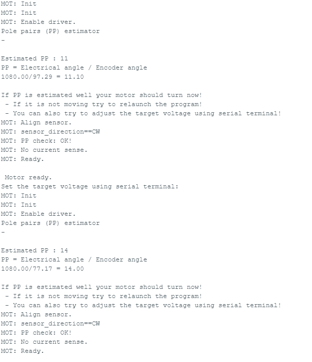
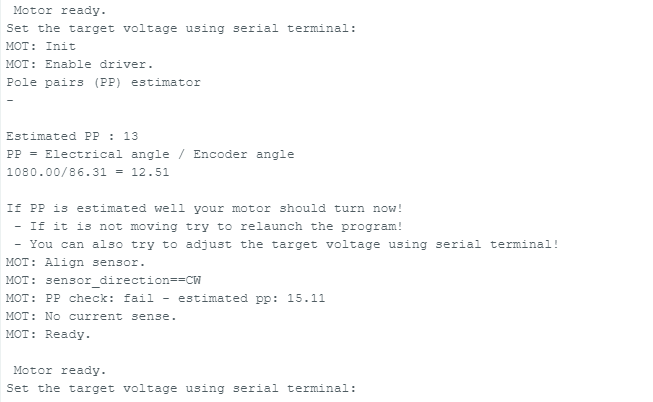
And I do 3 attempts and the results are:
So, for each attempt the PP are different, and I saw the electrical angle is always the same, but the encoder angle is different for all attempts.
@Jose_Aldahir_Espinos
That is an interesting result. The pole pair estimation changes with every run. The last run it changed just after the estimation finished. It seems that the encoder might be having an issue. Try using this code and turning the motor by hand. Use the serial monitor plotter so we can see how the values change. Arduino-FOC/examples/utils/sensor_test/magnetic_sensors/magnetic_sensor_i2c/magnetic_sensor_i2c_example/magnetic_sensor_i2c_example.ino at fb0be07488ed26db7cbc16dff0ef43c30bda818c · simplefoc/Arduino-FOC · GitHub Can you elaborate more on your set up? Where do you have the magnet and sensor located? A picture would be best. If the magnet or sensor is mounted wrong it could be causing issues. For example if the magnet or sensor is loose it might move during movement.
I will try this code and share my results.
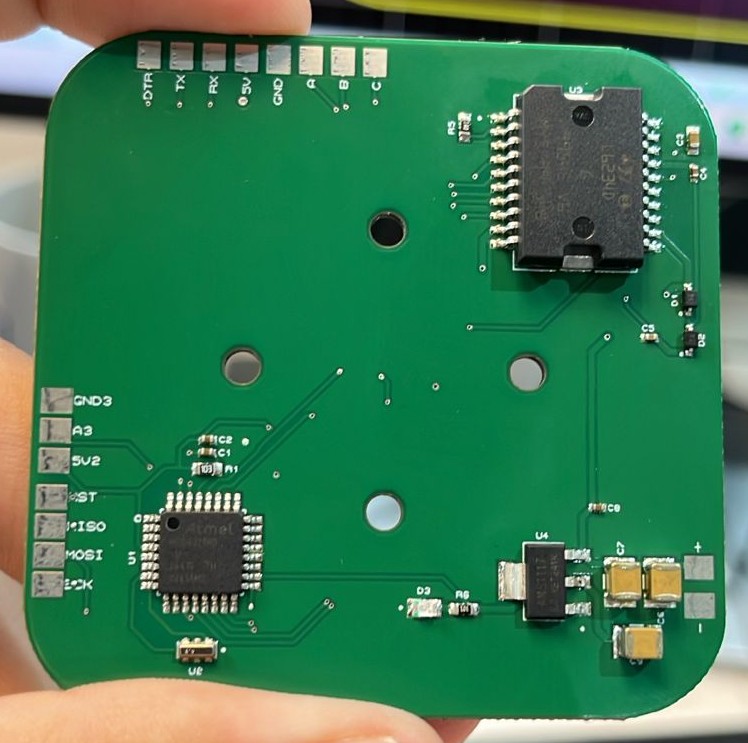
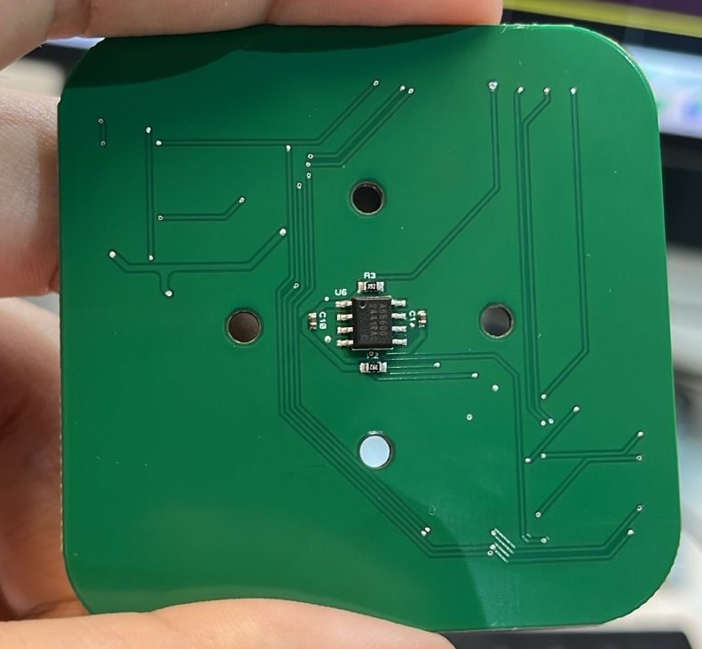
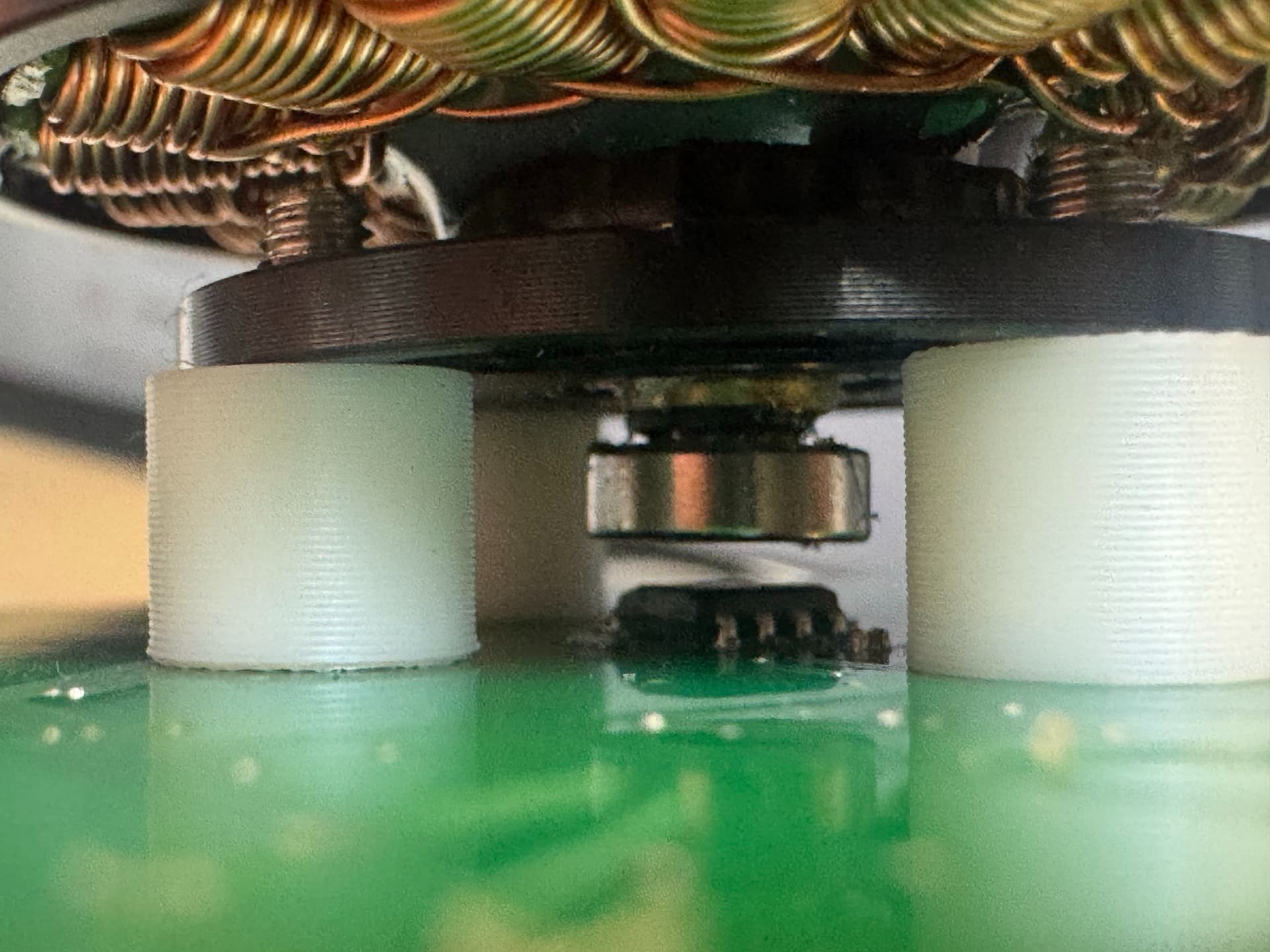
For my setup, I have a PCB, with an AS5600, L6234D and the Atmega328p.
The Atmega328p and the L6234D are in the top of the PCB and the AS5600 in the bottom, so I put the motor with the magnet in the bottom layer with a little pole of 1.8mm and the AS5600 is approximately 0.5mm to the magnet.