Problem with 6PWM driver mode run, IR2101

Hi, I’m working on an actuator using BLDC motor(24V, 5000rpm bldc motor with hall sensor). Yesterday I found simpleFOC library and i have change some of the connection of controller board and tried to spin.
But when I increased the voltage_limit, motor does not rotate as expected. When voltage 1, motor run very slowly but if I increase voltage 2 or more motor was wrong spinning. Previously I wrote a firmware for this controller, and same motor (using the hall sensor sequence, I made PWM pulse) I achieved 5000 rpm. But I can’t able to make good PID controlled that way I am thinking to use simpleFOC library.

Motor i’m using link
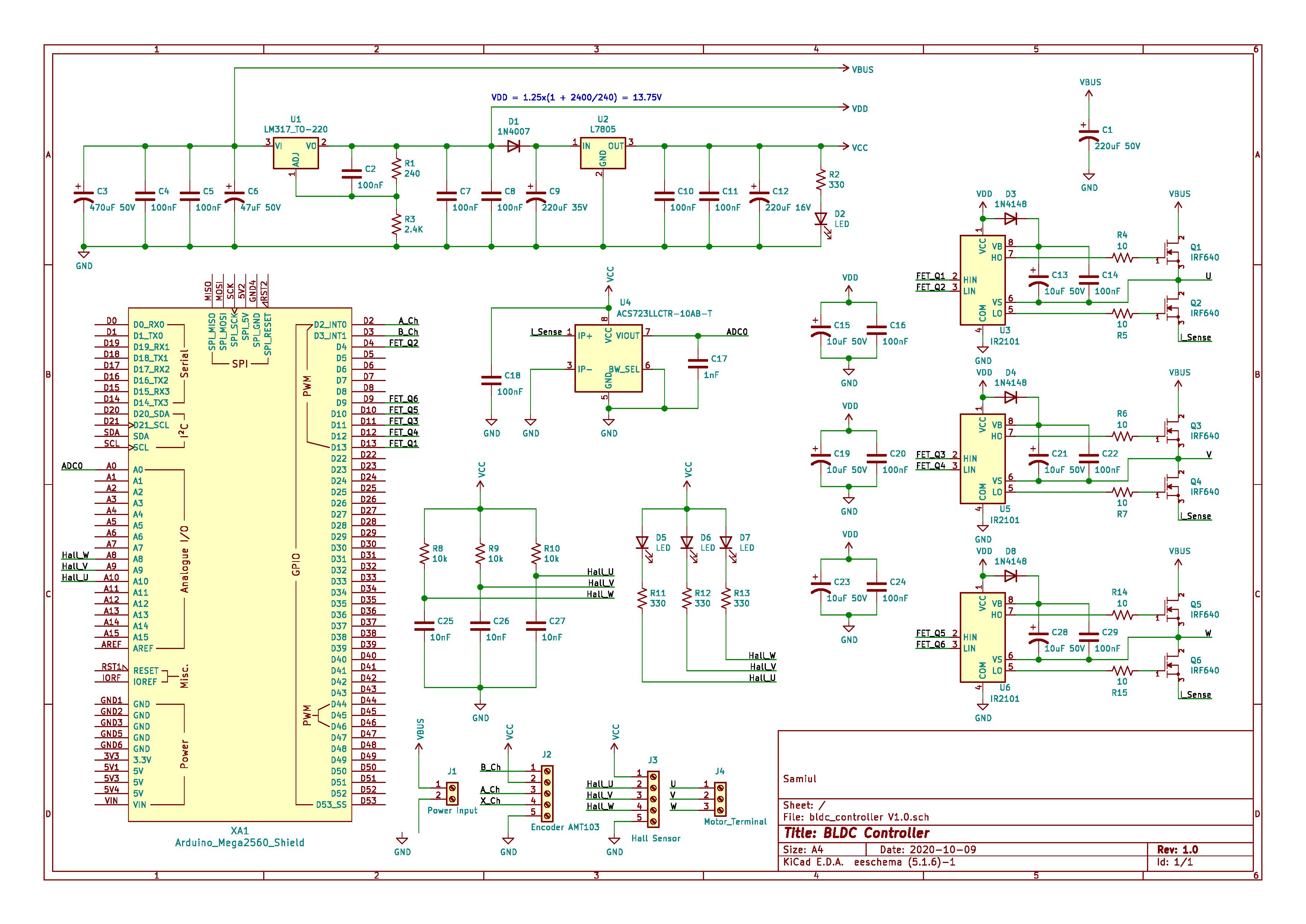
Here’s my test code, and circuit

// BLDC motor & driver instance
BLDCMotor motor = BLDCMotor(2);//13
BLDCDriver6PWM driver = BLDCDriver6PWM(13, 4, 11, 12, 10, 9); //( UH,UL,VH,VL,WH,WL) (3, 8, 2, 7, 5, 6) 13, 4, 11, 12, 10, 9

HallSensor sensor = HallSensor(A10, A9, A8, 2);//13


void doA(){sensor.handleA();}
void doB(){sensor.handleB();}
void doC(){sensor.handleC();}
// software interrupt
PciListenerImp listenA(sensor.pinA, doA);
PciListenerImp listenB(sensor.pinB, doB);
PciListenerImp listenC(sensor.pinC, doC);


float target=1.0;
void getCommand()
{
  static String received_chars;
  while (Serial.available()) {
    // get the new byte:
    char inChar = (char)Serial.read();
    // add it to the string buffer:
    received_chars += inChar;
    // end of user input
    if (inChar == '\n') {
      target = received_chars.toFloat();
      Serial.print("Tar= "); Serial.println(target); 
      // reset the command buffer
      received_chars = "";
    }
  }
}


void setup() {
  Serial.begin(115200);
  sensor.pullup = Pullup::EXTERN;
  sensor.init();
  
  // software interrupts
  PciManager.registerListener(&listenA);
  PciManager.registerListener(&listenB);
  PciManager.registerListener(&listenC);
  motor.linkSensor(&sensor);
  
  
  // power supply voltage
  // default 24V
  //driver.pwm_frequency = 32000;
  driver.voltage_power_supply = 24;
  driver.voltage_limit = 24;
  driver.dead_zone = 0.05;//0.2 // 5%
  driver.init();
  
  //link to the drive
  motor.linkDriver(&driver);

  // limiting motor movements
  motor.voltage_limit = 3;   // [V]
  motor.velocity_limit = 300; // rad/s 1 RPM = 0.10472 rad/s
  motor.voltage_sensor_align = 1;

  // open loop control config
  motor.controller = ControlType::voltage;

  motor.useMonitoring(Serial);
  // init motor hardware
  motor.init();
  motor.initFOC();

  Serial.println(">setup");
  _delay(1000);
}

void loop() {
  getCommand();
  
  motor.loopFOC();
  motor.move(target);

  motor.monitor();
}
1 Like

Hey @samiul,
Nice project!

Is this maybe and issue of alignment. Maybe 2 volts is too much for the motor to align properly. Too high current when motor is not moving.

You can add the line:

motor.voltage_sensor_align = 1; \\ default is 6V or driver.voltage_limit whichever is lower 

Otherwise I am not sure what could it be, if it is not the alignment.

Did you try to spin the motor in voltage control loop at 1 and at 2 volts?

What do you mean by wrong spinning? Perhaps a video link would be useful.

Can you try switching two of you motor wires around? There was a bug in halls that was recently fixed on dev that meant CCW hall wasn’t working reliably. (Or you could try dev branch)

Have you tried running it in openloop (don’t link the sensor + change controller = ControlType::velocity_openloop). Then in loop() print sensor.getVelocity() and sensor.getAngle() instead of motor.monitor(). Trying to establish if your motor and sensors are working correctly.

Hi,
@Antun_Skuric
@Owen_Williams
Thank you for your reply. And sorry for late reply.
I added 3 video (1volt, 2volt, 3volt)

I tried to switch between the two motor wires, no luck.
As you said at the beginning, I tried with open loop, but the motor doesn’t spin well.

is there any chance, motor pole pair is wrong(i found 2 using “find_pole_pairs_number.ino” with encoder)

I’ll let you know and try it on the dev branch.

Your 3 videos are voltage control mode, right?

I’ve seen something like this when i had hall interrupt issues. The hall’s behave fine with no motor running but get 1000s of interrupts when power is delivered to motors.

To fix this i used stronger 1k pull-ups. Perhaps your 10k are not enough.

To check whether this is your problem you can print ‘sensor.total_interrupts‘ in your loop() function. It should be incrementing pole_pairs * 6 interrupts per revolution. If your pullups are too weak it’ll be incrementing loads more.

Thank you for your reply,
Yes, all 3 videos are voltage control mode.
also check ‘sensor.total_interrupts‘, In 10 revolution I found 124 interrupt, i think it is okay isn’t it?

In addition I tried with dev branch. but same problem.

For 2 pole_pairs - 124 seems about right (expecting 120). Did you measure these 124 interrupts when it was ‘jerky’ i.e at 3V?

I’m not sure what else to suggest. Have you tried to use an oscilloscope and compare good 1V to bad 2V?

Do you get the same behaviour (but in opposite direction) with -1V and -2V?

1 Like