Hello, Everyone.
Firstly, thank you for everyone’s efforts into this project. This is the best dev community out there.
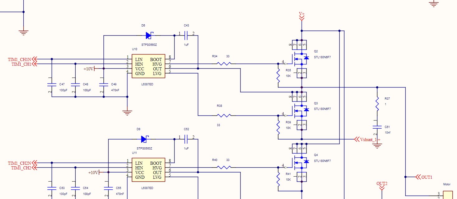
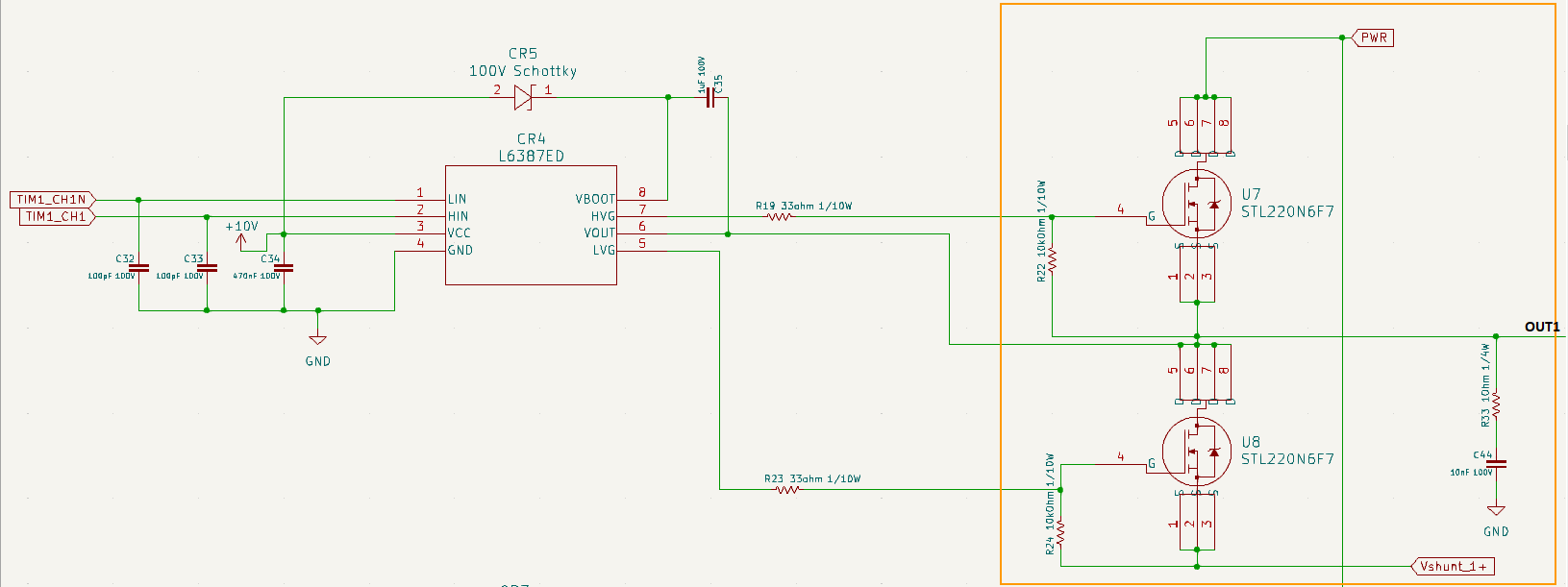
I’m attempting to build a custom board , based off of the B-G431-ESC1. Trying to use it for 56V and 10A. I’m not sure if I need to make any changes to the power stage section of the board, like the resisters for example. Below is the gate-MOSFET section of B-G431-ESC1 board for reference.
We can’t see the shunt part of the circuit, so can’t comment on that…
I’d say the left hand side capacitors are on the logic side, which will be 3.3V. Using 100V caps here is such a big overkill it might actually cause problems. Even if not, it will make the caps unnecessarily large and/or expensive. 16V caps is more than enough for 3.3V lines.
In terms of the gate resistance, starting with the same value as the B-G431-ESC1 is ok, but since you’re using different FETs you may also need different values for the gate resistance.
If you can mount the resistors yourself then it won’t be a problem to just try different resistance values empirically. If you’re having it assembled it might be good to do some math to check the value.
I was thinking of trying to do the same thing but with ~220 volts (for the diy 3khz vfd). I would probably use solid state relays, IDK if they can switch fast enough but I don’t see why not, they are just mosfets with an input stage. You can get em for like 6 bucks each and they are like 1 mosfet in an h bridge, so you would need 6 of them so kind of expensive but if you are only building one… Oh crap I’ve never been clear on the high vs. low side stuff. Presumably the gate driver takes care of that.
I would use a nucleo board for the processor part.
It is doubtful the SSRs are fast enough - maybe. The data sheets sometimes give the maximum switching frequency.
Be sure to get ones that are not “zero crossing” sensitive, or it won’t work at all.
Also, the SSRs I’ve seen have been for 220AC, but have a lower DC voltage and current capacity.
The AC ones are actually thyristors usually, aka silicon controlled rectifiers and as you say yes they don’t work quite right at the zero crossing. Thyristors get triggered and become conducting and they don’t stop conducting until current stops flowing through them. So they can work for controlling a light or motor power level if AC is used because there is the periodic reset when the AC signal gets close enough to zero, but they don’t work for DC. They would get stuck on. However you can gets ones that are suitable for DC, they are mosfets with an input stage, but they have the bypass diode so you can only put voltage across them one way of course. I bought a bunch and put them back to back to control an AC motor speed without the noise that the SCR types create (they make a buzzing noise). I haven’t actually tried my idea yet… and it’s separate from the VFD stuff.
Yes I need to check the datasheet, they are made for PWM though so hopefully it’s ok. There might be a capacitor on the input or something to filter noise which might scuttle my hopes.
Mine are rated for 220 volts DC, which I understand wouldn’t work for a 220 volt ac signal as the actual peak to peak is higher than that, but for 120 volts AC should be ok (so ac motor control) and possibly to produce a ~220 volt peak to peak signal. Actually that 220 VAC rating on the spindle motor is probably RMS, must be, so I wouldn’t be able to produce that even with SSRs but I don’t need full power…