I’m a newbie in this, but here are some hints from my short experience:
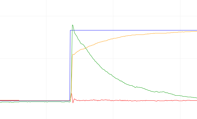
First you need to tune the velocity PID, because I think the angle control mode is based, underneath, on the velocity control mode. So set Motion Control to “Velocity” and look at the velocity curve when you suddenly change the velocity from 0 to X rad/sec. You need to achieve a velocity change that looks like the green curve here :
When the velocity PID is correctly tuned, you can get back to Angle Motion Control and tune the angle PID the same way. However, the angle PID is usually more simple, something like 20;0;0 (P only).
Would you please provide all your PID values? My guess is that you should increase “I” in the velocity PID.
Don’t be afraid if you don’t get very good result in Voltage mode. You need to start in Voltage mode in order to tune the Velocity PID then Angle PID in isolation. But then you’ll need to switch to Current modes to achieve better results (this will add more headache, though, cause this will add 1 or 2 more PIDs).
like you, I am a newbie to FOC and brushless motors but have a little understanding of control theory.
I tune the motor first in Voltage and Velocity modes and got a good response to step changes. It it is a fairly high-power Maxon motor currently running with no load. P =1.8, I=0, D=0. When I first went to angle control I got terrible oscillations even with it holding zero position. I found detuning the P term on the velocity controller down to 0.5 helped.
The P term on the angle controller is currently set to 3 if I increase it the oscillations come back.
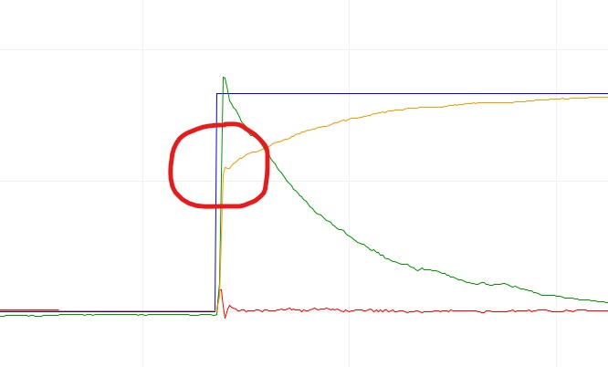
What looks strange is if you look at the response of the angle position (yellow) is very fast to respond but then slows causing a knee in the line.
You’ll have to tune your PID parameters. When setting up a motor with SimpleFOC, it is usually really helpful to start simple and get more complicated…
E.g. is your motor working as expected in open loop velocity mode?
Once that is working, add the sensor and start tuning your PID values for voltage mode. For a Maxon motor these could be quite different to the examples in the library.
Generally speaking, zero P, I & D, and increase P until you get as close to your target (velocity/position) as you can but without getting oscillations. Then increase I until you get a nice, quick response. D can usually be left on 0, sometimes it helps to set it to a very low value.
It is also conceivable that there is an electrical problem, for example the DRV8302’s OCP kicking in because the currents are getting too high. You could check this by monitoring the nOCTW pin. Or you could test your setup (with unloaded motor) with a lower voltage_limit so as to be sure the current stays in spec.
I assume the red line (voltage) is the output voltage as calculated by simplefoc?
Thanks runger for your input (anybody else feel free to jump in)
Yes, I have gone through all the basic steps, test the motor, driver and encoder. The motor seems to be working fine in open loop control. Although I had to keep the voltage low to stop excessive heating (but I think that normally for a low resistance motor in open loop)
As I said before the response in velocity control seems very good. If I increase P to high I do get oscillations.
You might be right about the DRV8302’s OCP kicking in. I try some more experiments. Current monitoring is next on my list of thing to try.
Yes you are right the red line is Volt_Q from the monitor line
Hey, wow, one month has passed - I’ve been so busy! Have you resolved this issue? It would be interesting to know if you got the Maxon motor working…
Looking at the red line, its interesting to see the rise and then the sudden dip. Since the V_Q is an output of the FOC algorithm, it means the algorithm is deciding to stop accelerating at the peak point, which correlates to the knee in the angle…
Sorry for the delay in replying. I have stepped away from Simple FOC for a while but am back now.
The short answer is NO I never resolved the issue but will be back revisiting it.
My setup has evolved a little in the fact that I am now using an ESP32 MCU my reason for using this is processor speed and I have ambistious targets for speed and control. I hope this is a good idea.
Yes, ESP32 is well supported. If possible, choose one with MCPWM support, so the older ESP32 Wrover, Wroom etc series, and not the S2 or C3, which do not have this support.
ESP32 is very fast, and has tons of communications options, it is a very nice MCU!
You don’t have to worry about the details if you choose the right chip, then SimpleFOC Library will handle everything for you transparently and internally. You’ll just be using the same BLDCDriver3PWM or BLDCDriver6PWM driver as usual for SimpleFOC.
Specifically the advantages of the MCPWM are:
it has what is called “dead time insertion” so it can do 6-PWM control. The normal PWM driver can only do 3-PWM control.
it will allow “centre aligned” PWM, the normal PWM can only do left-aligned PWM. Centre Aligned will lead to smoother motion and better behavior of the motor in some situations.
MCPWM is basically the correct tool for motor control, while the PWM we use on the S2 or C3 is more a kind of “hack”, and this PWM peripheral is not really intended for motor control.
ESP32-D0WD-V3
ESP32-U4WDH
ESP32-S0WD
ESP32-D0WD – Not Recommended for New Designs (NRND)
ESP32-D0WDQ6 – Not Recommended for New Designs (NRND)
ESP32-D0WDQ6-V3 – Not Recommended for New Designs (NRND)
ESP32-PICO-D4