Angle curve tuning - position control

Hi guys,

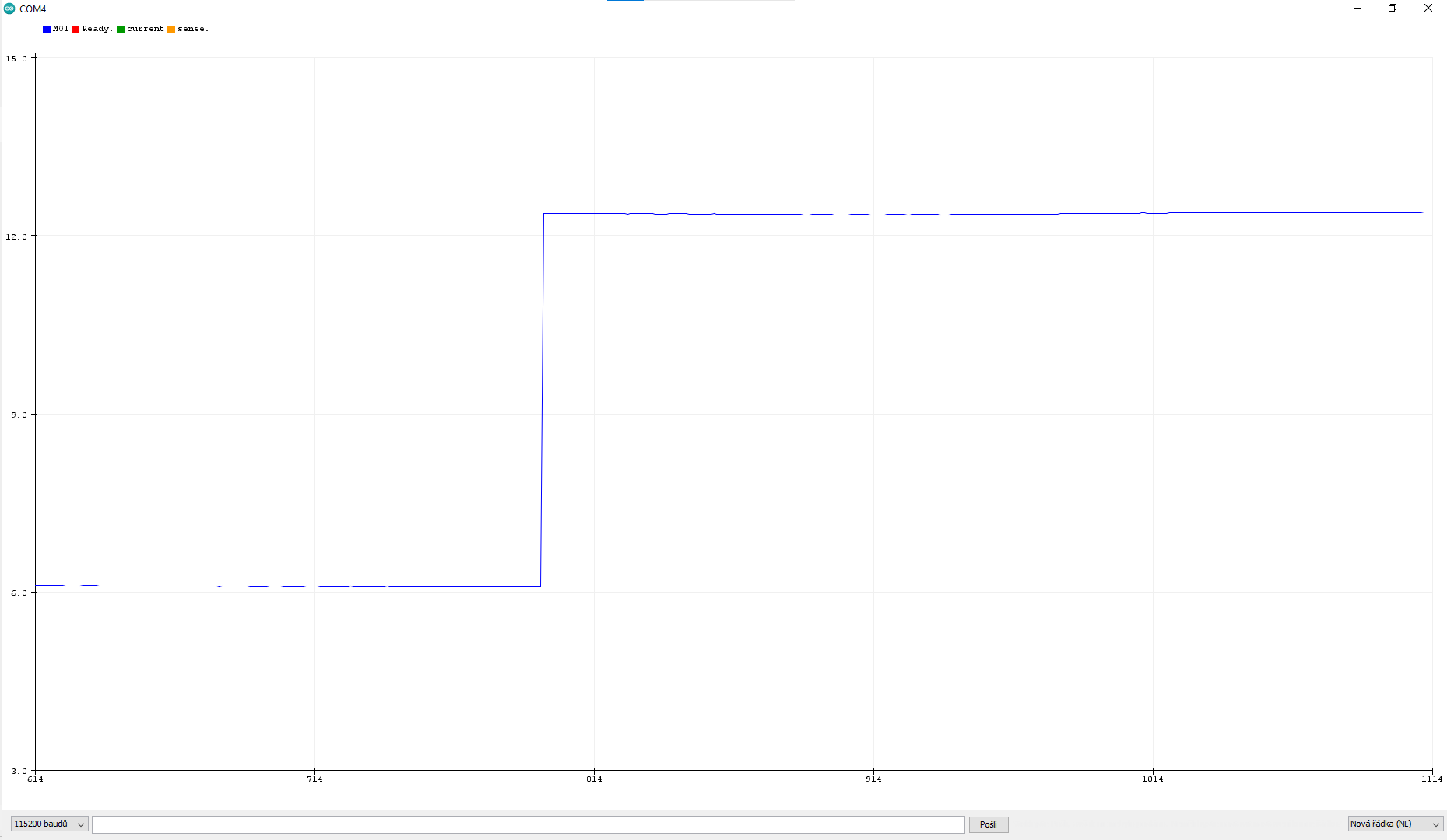
I have a question about position control that is most likely related to PID parameters tuning. I have a fully working motor setup in closed loop angle mode. The position control works ok, it just always seems to slow down dramatically before reaching the desired position.

It makes like 80% of the entire movement rather fast and than takes about the same amount of time for the remaining 20%. It looks like this:

I tried changing both velocity PID controller parameters and angle PID (only P and low pass filter constant). I also played with output_ramp setting, but nothing seems to reslove this.

Higher P values obviously make it go to the right position quicker, but at a cost of a relatively noticeable overshoot (which is not very acceptable for me)…

The curve looks something like this (orange one):


I borrowed the graph from this post.

I would like to get as close to the blue one as possible. Ideally make it behave
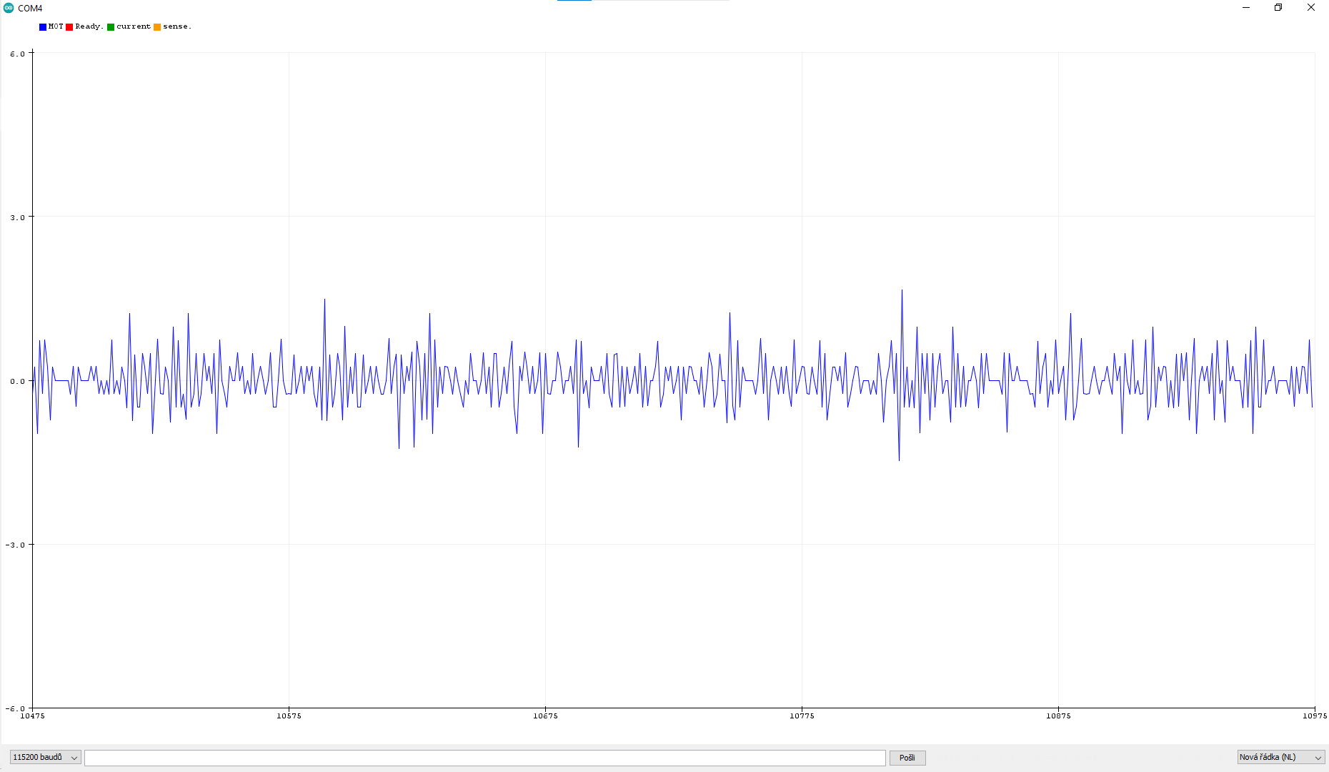
similarly to the open loop position control, which works super well and looks like this:

For completeness I am posting my closed loop code

#include <SimpleFOC.h>

// --- ENCODER ---
MagneticSensorI2C sensor(AS5600_I2C);


// --- DRIVER ---
#define INH_A 6
#define INH_B 5
#define INH_C 3
#define ENABLE A1

#define M_PWM 4
#define OC_ADJ A0

BLDCDriver3PWM driver(INH_A, INH_B, INH_C, ENABLE);

// --- BLDC MOTOR ---
#define POLE_PAIRS 20

BLDCMotor motor(POLE_PAIRS);

void setup() 
{
  Serial.begin(115200);

  SimpleFOCDebug::enable();

  sensor.init();
  motor.linkSensor(&sensor);

  // external driver setup
  pinMode(M_PWM, OUTPUT);
  digitalWrite(M_PWM, HIGH);

  pinMode(OC_ADJ, OUTPUT);
  digitalWrite(OC_ADJ, HIGH);

  // set driver voltage
  driver.voltage_power_supply = 20.0f;

  driver.init();
  motor.linkDriver(&driver);

  motor.foc_modulation = FOCModulationType::SpaceVectorPWM;

  // set torque control loop type and controller
  motor.controller = MotionControlType::angle;
  motor.torque_controller = TorqueControlType::voltage;

  motor.voltage_sensor_align = 0.6f;
  motor.voltage_limit = 2.5f;

  // velocity PID tuning (+ velocity limits)
  motor.PID_velocity.P = 1.1f;
  motor.PID_velocity.I = 6.0f;
  motor.PID_velocity.D = 0.01f;

  motor.PID_velocity.output_ramp = 300;
  motor.LPF_velocity.Tf = 0.2f;

  motor.velocity_limit = 8.0f;

  // angle PID tuning
  motor.P_angle.P = 4.0f;
  motor.P_angle.I = 0.0f;
  motor.P_angle.D = 0.0f;

  motor.P_angle.output_ramp = 15;
  motor.LPF_angle.Tf = 0.001f;

  // foc properties obtained through torque mode
  motor.sensor_direction = Direction::CW;
  motor.zero_electric_angle = 1.91f;

  motor.target = 0.0f;

  motor.init();
  motor.initFOC();

}

void loop() 
{
  if (Serial.available() > 0)
  {
    // PID tuning through serial line

    char component = Serial.read();
    float num = Serial.parseFloat();

    switch (component)
    {
      case 'P':
        motor.P_angle.P = num;
        break;
      case 'I':
        motor.P_angle.I = num;
        break;
      case 'D':
        motor.P_angle.D = num;
        break;
      case 'R':
        motor.P_angle.output_ramp = num;
        break;
      case 'F':
        motor.LPF_angle.Tf = num;
        break;
      case 'T':
        motor.target = num;
        break;
      default:
        break;
    }

    Serial.print("P: ");
    Serial.println(motor.P_angle.P, 3);

    Serial.print("I: ");
    Serial.println(motor.P_angle.I, 3);

    Serial.print("D: ");
    Serial.println(motor.P_angle.D, 3);

    Serial.print("R: ");
    Serial.println(motor.P_angle.output_ramp);

    Serial.print("Tf: ");
    Serial.println(motor.LPF_angle.Tf, 3);

    Serial.print("Target: ");
    Serial.println(motor.target);
    Serial.println();
  }

  motor.loopFOC();
  motor.move();
}

What I tried before posting this:

  • tuning the velocity mode separately (works very nice except changing speeds by setting motor.target. It just jerks to the new speed)
  • trying various P constants for angle mode (higher than 4 makes it overshoot, which is quite low compared to examples)
  • Measuring Atmega328p loops/second (I get around 700Hz with I2C set to 400kHz fast mode)
  • Repositioning the sensor and checking the magnet (correct magnet positioned as precisely as possible with 0.75mm gap between magnet and sensor)
  • Increasing motor’s voltage_limit
  • Increasing low pass filter time constant for both angle and velocity PID controller… Makes it even less responsive
  • Changing AS5600 polling time to “always on”
  • Enjoying nice movement of open loop :smiley:

Yeah, I tried a couple of things, but everything seems to make just worse, not better.

I would like to mention that I am using voltage_torque controller because my driver does not support current sensing right now. Could this be the issue?

I feel like this should be purely caused by the PID not being tuned correctly, but I spent more time than I am willing to admit on changing those.

Did anyone experience similar issues? I will appreciate every help now :smiley: .

Thanks,

Adam!

Higher angle P is the answer. The question is what’s causing the overshoot. Your velocity Tf is very high and likely a source of lag. I usually use .02-.05.

I would advise against using PID_velocity.D, unless you want to try editing the PID code. I think our current code only works properly when target is constant, due to a phenomenon called “derivative kick” http://brettbeauregard.com/blog/2011/04/improving-the-beginners-pid-derivative-kick/

Have you tried using PID_angle.I? I haven’t needed it, but it’s worth a shot.

Try plotting motor.getVelocity() while running at constant speed in velocity_openloop and see if it’s smooth. (that is, use open loop to produce smooth motion, and see if the sensor reads it as such, or is noisy)

EDIT: Also check how much time the sensor communication is taking, since it could also potentially be a source of lag between reality and the PID update. Paste this in MagneticSensorI2C.cpp and see what it prints out:

int MagneticSensorI2C::getRawCount() {
  // read the angle register first MSB then LSB
	byte readArray[2];
	uint16_t readValue = 0;
  // notify the device that is aboout to be read
uint32_t t0 = _micros();
	wire->beginTransmission(_conf.chip_address);
	wire->write(_conf.angle_register);
  currWireError = wire->endTransmission(false);
uint32_t t1 = _micros();
  // read the data msb and lsb
	wire->requestFrom(_conf.chip_address, 2);
	for (byte i=0; i < 2; i++) {
		readArray[i] = wire->read();
	}
uint32_t t2 = _micros();
static uint32_t lastPrintTime = 0;
if (millis() - lastPrintTime > 1000){
  lastPrintTime = millis();
  Serial.print("Write time "); Serial.print(t1-t0);
  Serial.print(", read time "); Serial.println(t2-t1);
}
  readValue = (readArray[0] & _conf.msb_mask) << _conf.msb_shift;
  readValue |= (readArray[1] & _conf.lsb_mask) >> _conf.lsb_shift;
	return readValue;
}

Yeah, my code could be out of date. But that velocity noise is definitely your problem, so I don’t think the I2C delay is worth worrying about.

Perhaps resolution is the issue? Assuming the actual speed is 1 revolution per second, that would be 4096/700Hz=5.85 steps per update. So some updates will see 5 steps and some 6, which is comparable magnitude to the noise you’re getting. But if that was the case, it should alternate between two values, not three.

Try plotting the angle while spinning at constant speed in open loop velocity mode and see if we can learn anything more from the stepping pattern. Or maybe sensor->getAngle() - motor.shaft_angle? i.e. the measured angle minus what it should be from the open loop setting, so the line isn’t perpetually moving upward and making the graph scale too high to see the small variations we’re interested in.

It does seem like most people have trouble with AS5600 and then change to one of those two, so probably not a bad plan to do the same.

I’ve only used hall sensors (digital and analog, the latter being my favorite). My machinery designs never have access to the end of the shaft for a magnet. Usually hollow shaft, or motor sticking off the end like this mini-spindle I made to regrind the chuck jaws on my lathe. I has a sensorless drone ESC, but if I did want to put a magnetic encoder on it, I’d have to make a ridiculous structure to reach around the motor and hold it over the end of the shaft.

I ditched the AS5600 to go with the AS5048A SPI, best decision ever made in my motor controlling career.

By the way, are you simply using the position control loop of the library? If so, then I can assure you can never eliminate that position jerk with PID only, at least not for arbitrary position target input by users. You can try as hard as you can tuning that PID, but the tuned parameters will only work for a small range of error.

What you want to do is to implement “motion profile”. Basically, you generate a set of position target as a function of time, for example a 3rd degree polynomial, then throw it into the motor.move(targetAngle) function. In that way, it will be easier for your PID. Imagine it’s like instead of telling your PID to go immediately from 0 degrees to 72000 degrees (200 revolutions), you tell it to go gradually from 0 to 360 to 720 to 1080 … to 72000.

What do you mean by real life example? I would give you a real life analogy: The PID is like a cab driver, and you are to tell the him to drive a taxi to your set-point position. Now the problem with this particular cab driver is that he doesn’t care about the car he is driving or how his driving behavior turns out to be when he hits the gas pedal. All he cares about is how far away he is from the current position to the target position you told him. He does not care about safety, car’s horse power, law of physics, passengers’ comfort. If he’s in Barcelona and you tell him to drive to Oslo, he will floor the sht out of that gas pedal and hold it like that until the cab eventually reaches its destination. And upon reaching that exact target spot, the driver will slam the sht out of the brake pedal. Basically, that’s what a PID controller do. Tuning the parameters is just adjusting the intensity of pedal slamming. The behavior in general will not change as much.

I didn’t take any courses in control theory, but I believe setting an instant target is referred to as “Step Target”, and what the PID controller attempts to do with that target is to generate a “Step Response”, meaning that it tries as hard as possible to reach that target instantly. From the analogy above, it’s like teleporting across Europe in less than a second, which in reality is not possible.

So when you think about setting target position to the motor, it’s very similar. If you tell it to go 180 degrees forward, it might go very smoothly, because the distance is not large, the driver is not flooring the pedals. But if you tell it to go say 720 degrees (2revs) immediately, you might see something like in your video, where the motor jerks a lot at first (because error now is very large), then as the error lessen, it slows down. That’s the behavior of the motor under the effect of the PID controller, which the controller itself doesn’t care about.

So, by using a function to generate target position, it’s like you continuously telling the cab driver to drive by 100 meters every few seconds until the destination. The motor.move(…) function is doing exactly that. In some BLDC servo applications, it is referred to as “Cyclic Synchronous” mode. Here, have a look at a German Brushless driver’s manual: Circulo Driver, page 606 of the PDF file, Modes of Operation.

For motion profile, you can implement a simple 1st order linear ramp of target, something like:

// Your other code ...

float generateTargetRamp(float currentPosition, float targetPosition, uint32_t *millisecondNow)
{
    // Use linear interpolation to solve for f(t) = a.t + b
    float outputTarget = a * (*millisecondNow) + b;
    return outoutTarget;
}

void loop()
{
    timeNow_ms = millis() - timeStart_ms;
    // Go from current angle to 7200 degrees:
    float targetDeg = generateTargetRamp(motor.shaftAngle(), 7200.0f, &timeNow_ms);
    float targetRad = // Convert deg to rad, I believe the library sets position as radians
    motor.move(targetRad);
    motor.loopFOC();
}

Regarding the noise in velocity reading, it looks fine to me, that’s not really your problem. SimpleFOC does have a LowpassFilter for velocity. If you love having it smooth, try cranking up the filter.

About this, I no longer use SimpleFOC so I don’t have any code other than what suggested above to share, sorry. I just love the community, and my FOC journey started from this very lovely library.

Sorry, I’d forgotten about this thread.

The sensor.getAngle() - motor.shaft_angle graph is meaningless. I forgot open loop wraps the angle, so the graph gets a step of 2pi and the small ripple we’re interested in is too small to see.

And if you printed motor.shaft_velocity in open loop mode, the reason it’s constant is because it’s not being updated from the sensor.

But if getVelocity is just as noisy when sitting still, you can simply plot sensor->getAngle(). Then do one of motor.shaft_velocity in closed loop torque mode with target 0 (this mode will update the velocity lowpass). If it’s reasonably smooth with the default 0.02 time constant, then maybe this level of getVelocity noise is normal and you can just ignore it.

Velocity is the time derivative of angle, so noise in the angle may be amplified. Perhaps we should be filtering the angle first and calculating the velocity from that… my math intuition is not good enough to say whether it would be smoother or not.

Just like @dekutree64 said, the velocity noise is indeed amplified by the noise in position. This is because of the nature of magnetic sensors, and the only way to resolve this is by applying digital filters. Empirically for magnetic sensors, at stand still, if the degree of noise for position is less than 0.5 degrees then you shouldn’t need a filter for position. The velocity reading, however, often requires filtering for smooth operation. You can go with the library’s LPF, or you can implement more advanced observers, say like a Kalman Filter.

Regarding the behavior of the motor in open loop mode, the reason you saw that it moved with constant velocity throughout its entire trajectory is because no PID is applied, and the PWM is sent at a constant value until the target is reached. You can achieve something very close to this result by overdamping your PID by a lot. First turn all P I D to 0, then slowly bring up the P alone, to the point where the motor starts moving without jerk but could not reach the target, because the P gain is not enough to move the motor through though final error range. Then, with this P threshold, take a new P value of around 40% of it. Apply that 40% P, add a bit of I value of 0.1% of that 40%P. At this point, you should be very close. If the motor overshoots its target, reduce P by a bit, if it undershoots, increase I just a bit.

I tried using I (even D :D) in the PID_angle. The I component seems to slow down the overshoot correction in my case.

I’ve set PID_velocity.D to zero as you advised (quite interesting thing the derivate kick, didn’t know it existed). It has very little to none effect on my velocity_control, but makes the angle mode bit more shaky during movement.

But the velocity Tf you mentioned has enormous effect. Value of 0.05 makes my motor shake like … :smiley: (though, 0.1 seems to work sort of ok). Is this related to sensor noise?

Well, I think that this is pretty bad :smiley:

I used open loop velocity mode to turn the motor at 7.0 rad/s, which seems very smooth to me, but this is how it seems to the sensor.

I used separate instance of MagneticSensorI2C and getVelocity() function in the open loop code (hope that’s right). Can’t really use the fancy commander thing, since the arduino seems pretty slow for that.

I’ll try to print out the communication delay as well, but this is most likely it :smiley:

EDIT:

I think you may have some modified version of the source code… My version does not include any definition of _conf property in MagneticSensorI2C class :sweat_smile:

Yeah, plotting the angle seems like reasonable next step! Unfortunately college week is starting for me, so I am away from the setup for a while :sweat_smile:.

Nevertheless, I will try to get a new and perhaps better magnetic sensor during the week. So if the cheap AS5600 turns out to be the problem I will have something else to replace it with. (+ SPI interface might improve the loop time if nothing else)

Do you have any experience with AS5047 vs AS5048A?

Thanks for the great assistance, I will reach out with the graphs in a few days!

Hi, I apologize for the delay (I have a ton of stuff at school…). Nevertheless, I found some time to get the new graphs.


This one is a plot of sensor.getAngle() - motor.shaft_angle… The steps seem to pretty “clean” to me. But clean doesn’t mean right. It seems quite a bit larger than it should be.

I tried to resolve the velocity noise by replacing the sensor with the mentioned AS5048A but the problem still persists. The sensor.getVelocity() plot for AS5048A looks like this:


It remains basically unchanged… The funny part is, that the motor doesn’t even need to spin for the noise to occur. This particular screenshot was taken while the motor had its motor.target set to 0.

Is this normal? Can’t this be just some issue of the getVeolcity() function? If I print motor.shaft_velocity, it is perfectly constant.

I tried to run it in closed loop despite the noise, but forgot to retune the PID values for the new sensor, so I just burned the motor :joy: :sweat_smile:. I am really running out of ideas! Thanks for any advice!

Do you have any real life example of this? Perhaps some SimpleFOC code that you are willing to share??

I would really like to look into this after I resolve that super annoying noise problem.

Thanks for the analogy! I feel like I have a good understanding od the techinique now.

Do you really think that such a horrible noise can be just “low passed” and ignored? From the discussion with @dekutree64 I came to a conclusion that this is a major problem that makes the motor sluggish…

I fully understand that it is quite impracticle for real life use, but I want to move as close to the open loop behavior as possible. Using your great analogy → full gas → full brake (expecting some overshoot that will later be removed by motion planning) .

I just want as quick response as possible for now.

Hi guys,

sorry for my long disappearance (had an examination period at uni)… Nevertheless, I think the so called “motion profile” was the answer to my problem. I’ve implemented simple ramp profile as advised, which made raising the P gain possible.

I still need to have the LPF constant (for both velocity and angle) rather high (0.1 for both). But hey, it works :D. I think that the last issue might be hidden in the magnet choice. Even thought I am 100% sure that it is the correct type, it just might be of low quality or something. Maybe I’ll try to replace it in the future.

Here is a video of the result:

And my code (hope it helps someone with similar issue :D)

#include <SimpleFOC.h>

// --- ENCODER ---
MagneticSensorSPI sensor(AS5048_SPI, A5);


// --- DRIVER ---
#define INH_A 6
#define INH_B 5
#define INH_C 3
#define ENABLE A1

#define M_PWM 4
#define OC_ADJ A0

BLDCDriver3PWM driver(INH_A, INH_B, INH_C, ENABLE);

// --- BLDC MOTOR ---
#define POLE_PAIRS 20

BLDCMotor motor(POLE_PAIRS);

// motion profile
void generateProfile(float currentPos, float desiredPos, float timeToReach); // time in seconds
float readProfile(unsigned long timeFromStart);
unsigned long startTime;
float moveDurationTime;
float desiredTarget;

float k = 0.0f; // parameters of linear interpolation (y = kx + q)
float q = 0.0f;

void setup() 
{
  Serial.begin(115200);

  SimpleFOCDebug::enable();

  sensor.init();
  motor.linkSensor(&sensor);

  // deselect CAN interface SPI device
  pinMode(10, OUTPUT);
  digitalWrite(10, HIGH);

  // external driver setup
  pinMode(M_PWM, OUTPUT);
  digitalWrite(M_PWM, HIGH);

  pinMode(OC_ADJ, OUTPUT);
  digitalWrite(OC_ADJ, HIGH);

  // set driver voltage
  driver.voltage_power_supply = 20.0f;

  driver.init();
  motor.linkDriver(&driver);

  motor.foc_modulation = FOCModulationType::SpaceVectorPWM;

  // set torque control loop type and controller
  motor.controller = MotionControlType::angle;
  motor.torque_controller = TorqueControlType::voltage;

  motor.voltage_sensor_align = 0.6f;
  motor.voltage_limit = 3.0f;

  // velocity PID tuning (+ velocity limits)
  motor.PID_velocity.P = 0.9f;
  motor.PID_velocity.I = 6.0f;
  motor.PID_velocity.D = 0.0f;

  motor.PID_velocity.output_ramp = 300;
  motor.LPF_velocity.Tf = 0.1f;

  motor.velocity_limit = 8.0f;

  // angle PID tuning
  motor.P_angle.P = 7.0f;
  motor.P_angle.I = 0.0f;
  motor.P_angle.D = 0.0f;

  motor.P_angle.output_ramp = 30;
  motor.LPF_angle.Tf = 0.1f;

  // foc properties obtained through torque mode
  motor.sensor_direction = Direction::CCW;
  motor.zero_electric_angle = 2.2f;

  motor.target = 0.0f;

  motor.init();
  motor.initFOC();

}

void loop() 
{
  if (Serial.available() > 0)
  {
    // PID tuning through serial line

    char component = Serial.read();
    float num = Serial.parseFloat();

    switch (component)
    {
      case 'P':
        motor.P_angle.P = num;
        break;
      case 'I':
        motor.P_angle.I = num;
        break;
      case 'D':
        motor.P_angle.D = num;
        break;
      case 'R':
        motor.P_angle.output_ramp = num;
        break;
      case 'F':
        motor.LPF_angle.Tf = num;
        break;
      case 'T':
        desiredTarget = num;
        moveDurationTime = abs(motor.shaft_angle - desiredTarget) * (1.1f/(2*PI));
        generateProfile(motor.shaft_angle, desiredTarget, moveDurationTime); // 2pi rad takes around 1.5 seconds
        startTime = _micros();
        break;
      default:
        break;
    }

    Serial.print("P: ");
    Serial.println(motor.P_angle.P, 3);

    Serial.print("I: ");
    Serial.println(motor.P_angle.I, 3);

    Serial.print("D: ");
    Serial.println(motor.P_angle.D, 3);

    Serial.print("R: ");
    Serial.println(motor.P_angle.output_ramp);

    Serial.print("Tf: ");
    Serial.println(motor.LPF_angle.Tf, 3);

    Serial.print("Target: ");
    Serial.println(desiredTarget);
    Serial.println();
  }

  if (_micros() - startTime >= (unsigned long)(moveDurationTime * 1000000)) // should be shaft angle probably
  {
    motor.target = desiredTarget;
  }
  else 
  {
    motor.target = readProfile(_micros() - startTime); 
    // Serial.println(motor.target);
  }

  motor.loopFOC();
  motor.move(); 
}

void generateProfile(float currentPos, float desiredPos, float timeToReach)
{
  // x1 = 0 (time starts at zero)
  // y1 = currentPos

  // x2 = timeToReach
  // y2 = desiredPos
  
  k = (currentPos - desiredPos) / -timeToReach;
  q = currentPos;

  Serial.println(k);
  Serial.println(q);
}

float readProfile(unsigned long timeFromStart)
{
  float t = timeFromStart / (float)1000000;
  return k * t + q;
}


So thank you @dekutree64 and @An_Hoang for your help!!

Adam