I’ve searched the forum and have been unable to find an answer to my question so here goes.
Firstly some background. I’m attempting to replace the 1970’s PLL of a Technics DD turntable with FOC. The motor is a 20 pole PMSM with 2 inbuilt sensors. One sensor is an FG (frequency generator) which outputs approx 0.3Hz/RPM. The other sensor (rotation sensor) requires an excitation (50kHz) and amplitude modulates a 3 phase (NOT the motor drive) signal which the electronics uses to drive the motor.
The current electronics has excellent dynamic speed stability in the order of 100ppm and the goal is to at a minimum match this figure. The motor is spinning with open loop control but speed stability is not as good as the OEM so I’m looking at ways to close the loop using the internal sensors for rotor position.
I do not want to add sensors to the motor. So my question is - can the FG signal be used and conditioned to provide accurate rotor position information.
I’m pretty sure I could use the rotation sensor but this requires 50kHz excitation and AM demodulation.The demodulated signal is a factor of 10 of the rotation speed.
Could you please define speed stability metrics and how you measure it.
When you say “motor position” you mean radial velocity, not absolute angle position?
Generally the answer is to stick to open loop, it gives the best radial/angular velocity stability.
I have done estimates, you can get down to to about 0.2% StD of the target velocity.
Sensoring and closing the loop increases your error.
Any sensor would introduce an error, since open loop doesn’t care and only follows the internal MCU clock. I’m surprised you weren’t able to beat the original setup with open loop. Especially a turntable with such large angular momentum. What MCU/driver you used to turn the motor?
I measured speed stability of the OEM setup by FM demodulating the FG signal both statically (platter spinning) and dynamically (playing a record). I have a reference of 0.0107% static and 0.0110% dynamic we’ll call this Wow & Flutter, I then used a phone app as a quick and dirty check which corresponds to my FM demod on the stock unit
I mean radial velocity not absolute angle.
I have open loop kinda working. The platter rocks back and forth and needs assistance to commence rotating at 33.33RPM then takes nearly a minute to stabilise at which time I used the phone app to check stability which is 0.13% Wow & Flutter.
I’m not worried about speed accuracy ATM I know this can be tuned by rad/s what I need to achieve is speed stability.
I have a Uno and STM32 black pill driving a SimpleFOC shield V2.0.4.
Add more bulk capacitance. This will eliminate any voltage ripple.
Ensure extremely stable voltage supply. Same as above.
Increase the voltage or current or both. This will increase the magnetic force counteracting any mechanical vibrations/oscillations.
Transition/graduate to a fully integrated driver with high quality components. This will eliminate any noise and error in the PWM in the MCU and driver/mosfets. This is also the hardest, as it will take time and be expensive. We did the SimpleFOC shield for educational purposes. You are truly pushing the limits here.
Once you do all four you should be able to hit the target (or get really close I believe).
The best I have seen is 0.4%. You hitting 0.1% with an educational setup made of Chinesium components is remarkable already.
Also, you need to add a small spin-up algorithm to slowly increase and decrease velocity in open loop, but I’ll help you with that, I’ve done it for other projects, and this is your least concern.
There are mechanical components that could be added such as a tungsten flywheel but that would modify the physics of the platter and I assume you don’t want to touch that. Your platter is most probably suspended by a finely tuned damper system and this will f*ck it up. Also cover the spinning platter with a fully enclosed lid to prevent any air movement interference from outside, probably already done? Place the system on a solid piece of granite slab, probably already done?
I was running the shield from my Lab power supply this is an old one I’ve had on the bench for 40 years and is very clean. It’s able to supply 30V @ 1 amp. I did swap to a Mean Well SMPS 24V 10A with zero difference.
I have current_limit set at 1A and also tried 1.5A
and voltage supply and limit set at 24V
Motor is Wye configuration and phase resistance is 13.2R this is from phase to neutral.
Motor has perfect sinusoidal BEMF.
monitoring motor phase current it peaks about 600mA.
Motor drive waveform looks like a 2 step squarewave. I would have expected something approximating a sinewave.
I must hit 0.01%, dynamic there is no point in down grading the drive system. This was proof of concept then I would design and build dedicated drive electronics.
I thought I’d give FOC a go in an attempt to reduce the footprint of the electronics. You can imagine the physical size of an all analog PLL.
I was under the impression that FOC was developed to reduce torque ripple. I’m interested to understand why open loop would be superior to closed loop in a system with varying dynamic load.
My TT sits on a Minus K isolation platform in another room from the system. So it’s as well isolated from the environment as is possible in my house.
When the stylus is in the groove the load varies significantly with modulation. Tests have been performed that show this load. A TT manufacturer called Kuzma used his top TT with air bearing. The unpowered 60kg platter spun for 30hours until it came to a stop. With the stylus in the groove the platter stopped in 20 minutes and the rundown time varied with records.
Not sure if I posted the code correctly I couldn’t find how
#include <SimpleFOC.h>
//define Pinout #define phA PB1 //PWM_A Arduino Pin 9 #define phB PB0 //PWM_B Arduino Pin 5 #define phC PA7 //PWM_C Arduino Pin 6 #define en PA6 //Enable Arduino Pin 8 #define senA PA1 //current sense phase A Arduino Pin A0 #define senB PA2 //current sense phase B Arduino Pin A2 #define PP 10 // Motor pole pairs verified #define Re 13.2 // Motor winding resistance measured #define Kv 14.3 // Motor Kv neasured
// BLDC motor instance BLDCMotor(polepairs, (R), (KV))
BLDCMotor motor = BLDCMotor(PP, Re, Kv);
// inline current sense instance InlineCurrentSense(R, gain, phA, phB, (phC))
InlineCurrentSense current_sense = InlineCurrentSense(0.01, 50, senA, senB);
The issue most setups have is that the FOC requires position input, and thus a sensor.
When using velocity mode, velocity is computed as the differential of position, introducing errors due to both time and position errors. These are typically additionally amplified by PID and filter settings leading to oscillation.
In terms of speed stability it is both this and the cogging of most motors that lead to poor speed stability.
But you have sensors available giving you accurate velocity signals, a motor well suited to the use case and presumably plenty of inertial mass on the turntable… so if you’re up for a bit of hacking, coding and experimentation then you may get better results…
You’ll want a high bandwidth controller to get as much fidelity as you can, I would assume. So definitely use the BlackPill and put the UNO aside for less demanding tasks… you may even want to consider upgrading to a Nucleo64 board based on the STM32G4 series, they not expensive. Try to find one with an external oscillator for better clock accuracy.
try to find a low latency position sensor, with ABZ interface for low latency transfers.
Then see how you go just with that for starters.
Afterwards we could see about adding the velocity control loop, but using the built in sensor you mention. For that, it sounds like we’d need to find a way to interface it electrically and in software.
And have you searched “turntable” in this forum? There’s been a couple of turntable projects in the past year…
I’m running the motor with the Black Pill the Uno was only used until the BP arrived.
The cogging of the SP10 motor is very low and un-energised almost non-detectable. It uses IPM and variable air gap to minimize effects of cogging torque. I suspect I won’t need to add anticogging algorithm.
I have 2 sensors available. Speed via frequency generator and rotor position via 3 VR sensors spaced 120deg around the rotor. The position sensors use a 50kHz excitation and provide after AM demodulation a frequency 10 times that of platter rotation speed. So the motor is a generator as well that provides a 180ms sinewave that drives the motor at 33.33rpm.
One thing I do not want to do add additional sensors, as this is not an easy task. The sensor would need to be non contact and external to the motor making the sensor 150mm in diameter.
I have designed a circuit to provide the 50kHz with an active envelope detector to demodulate the AM. I was thinking if I sawtooth this feedback I should be able to use it for accurate rotor position. I’m an old analog guy so this bit is easy, how to do the code is not my forte.
I guess the whole point of me posting here was to determine that what I was proposing is possible within the constraints of the OEM motor sensors.
The problem is the accuracy on this signal - it may be enough using interpolation on the sine wave…
You said the motor has 20 poles, so this 10x signal corresponds to the electrical rotations of the motor, since the motor has 10 pole pairs.
In any case I guess you’d want at least an 8 bit interpolation on the sine signal to recover an accurate position.
There’s no shaft exposed on the back that you could stick a magnet on?
Nice!
This could work… you’ll have to watch out that offsets or reference voltages don’t cause a discontinuity on the switch from 360-0deg. That would be exactly the kind of thing that would introduce speed stability issues, having a once per electrical revolution “blip”…
You could also sample the three phase voltages, and use a transform to recover the position from these directly?
This is interesting I hadn’t thought of that. I’ll do some research
There is no exposed shaft to place a sensor on.
This signal is generated by a copper ring on the FG rotor and is very accurate. It’s used by the Technics circuit to generate the motor drive signal. The ones I’ve measured are 180ms and stable to better than 0.5ms. Some of this instability could be the simple diode detector and oscillator the OEM electronics uses.
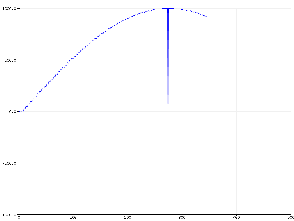
My thought was to use one of these outputs after demod use a schmitt trigger to squarewave then through a x10 multiplier. This will give a sawtooth per revolution of the motor with the voltage magnitude representative of rotor position.
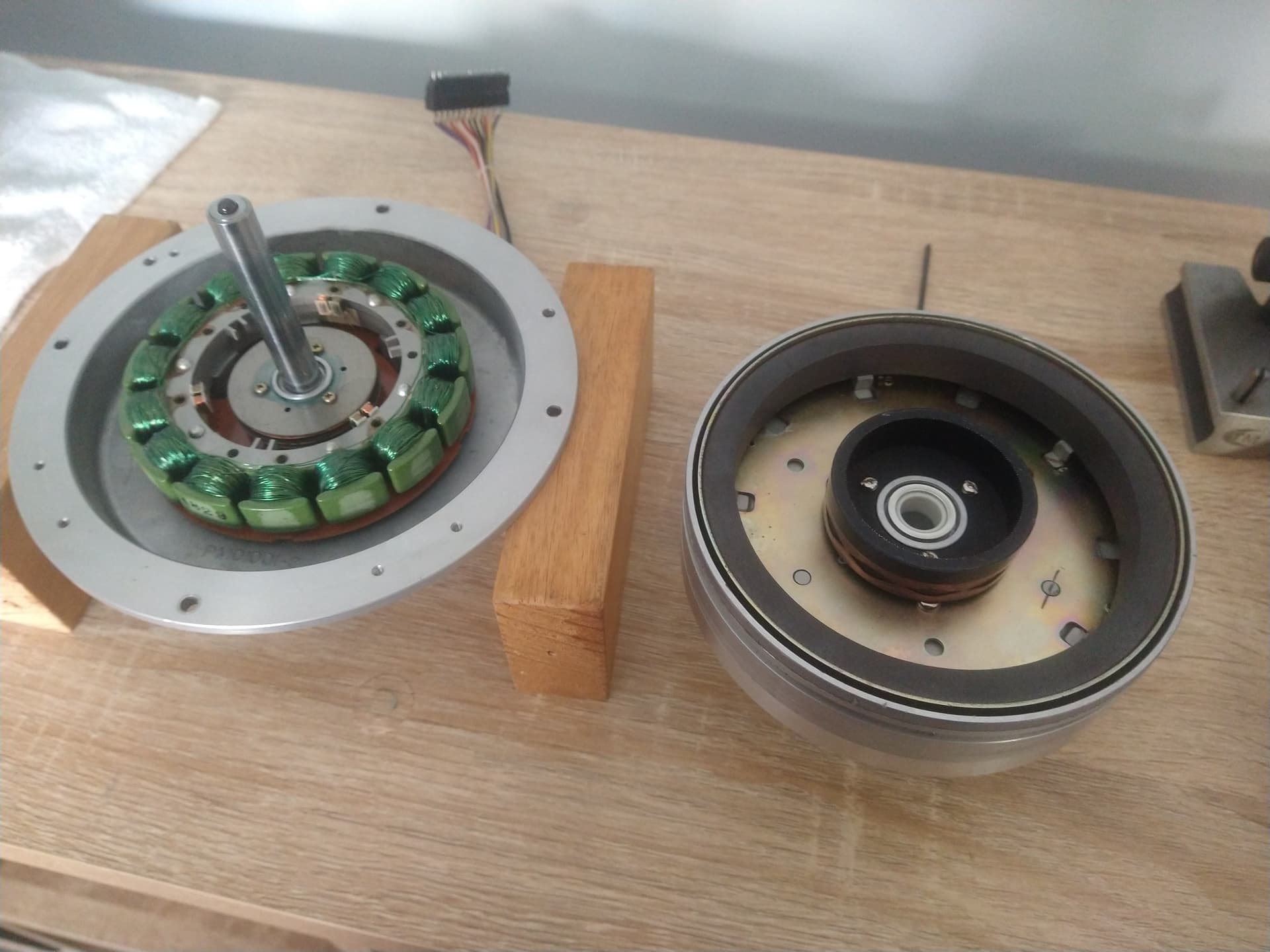
Here’s the inside of a modified motor. You can see the copper ring on the inner FG rotor. On the stator the 3 VR sensors are visible The FG rotor and magnet are keyed to the rotor housing to maintain alignment. The mounting holes in the FG rotor are slotted and there is a reamed alignment hole