I’ve tried your library, erwin74’s code also (https://community.simplefoc.com/t/can-bus-support/407) still have nothing looks like data is added to queue, but isn’t send at all (monitoring bus on osciloscope). I tried different clock setting, including FDCAN source (PLL, HSE, PCLK), various build flags, init values for FDCAN based on my stmcube and on Your libraries.
in stmcube it works good (i’m sure that hardware works), in plarformio i did working internal loopback mode, but normal mode doesn’t work :C
Is the first one stmcube and the second using arduino? There are plenty of reasons that boil down to the peripheral registers are unlikely to be setup identically. I’d export the peripheral registers from the known good one (stmcube) and compare to the one that doesn’t work (arduino).
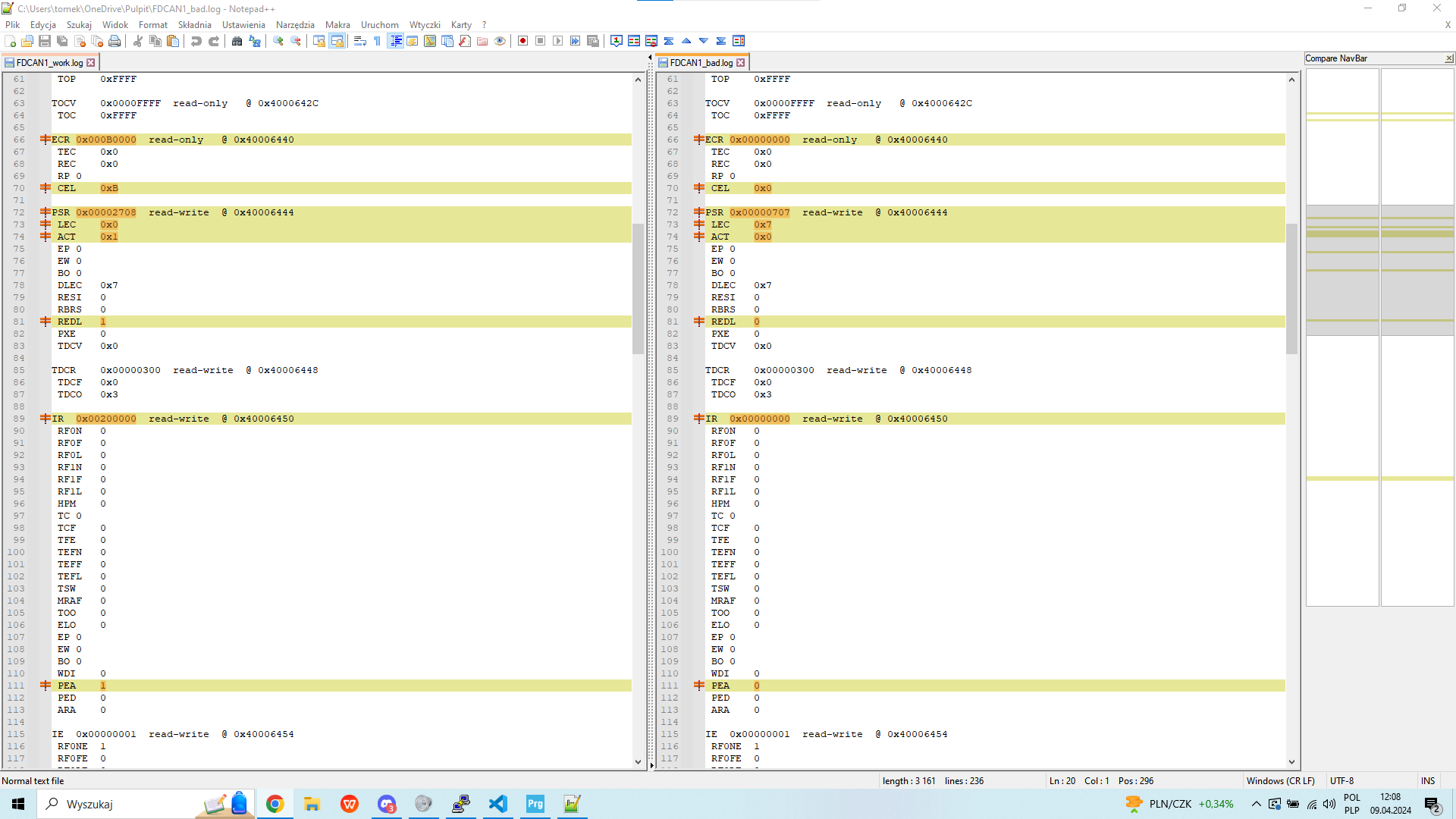
Here is an example of me comparing registers from two firmwares:
Ignore the details in the picture, but where there are differences - you can look them up in the stm datasheet and see if the difference is likely to be important. I’d look at clock registers (RCC *) as well AS CAN1.
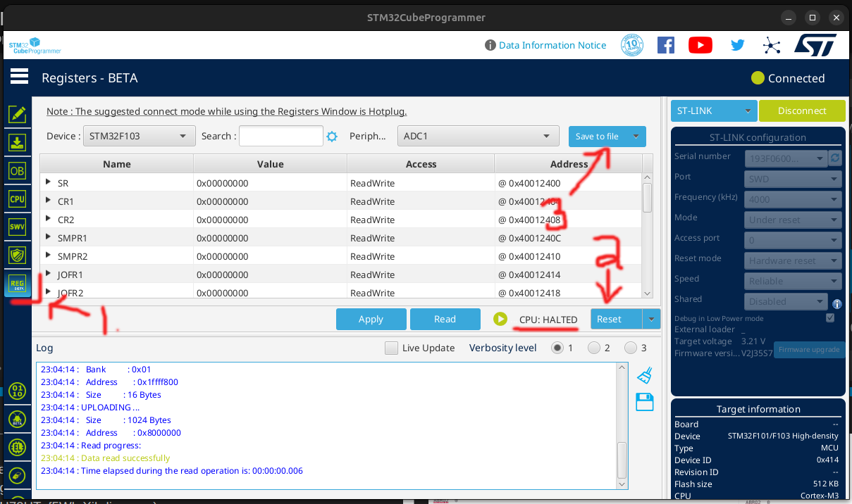
You can export Peripherals registers using stm32 programmer, note: before ‘Saving to file’ you need to reset otherwise the mcu will be halted before setup code has run
#include "myCAN.h"
#include <Arduino.h>


FDCAN_HandleTypeDef hfdcan1;
FDCAN_TxHeaderTypeDef TxHeader;
FDCAN_RxHeaderTypeDef RxHeader;

uint8_t RxData[64];

void MX_FDCAN1_Init(void)
{

  /* USER CODE BEGIN FDCAN1_Init 0 */

  /* USER CODE END FDCAN1_Init 0 */

  /* USER CODE BEGIN FDCAN1_Init 1 */

  /* USER CODE END FDCAN1_Init 1 */
  hfdcan1.Instance = FDCAN1;
  hfdcan1.Init.ClockDivider = FDCAN_CLOCK_DIV2;
  hfdcan1.Init.FrameFormat = FDCAN_FRAME_FD_BRS;
  hfdcan1.Init.Mode = FDCAN_MODE_NORMAL;
  hfdcan1.Init.AutoRetransmission = ENABLE;
  hfdcan1.Init.TransmitPause = DISABLE;
  hfdcan1.Init.ProtocolException = ENABLE;
  hfdcan1.Init.NominalPrescaler = 1;
  hfdcan1.Init.NominalSyncJumpWidth = 2;
  hfdcan1.Init.NominalTimeSeg1 = 53;
  hfdcan1.Init.NominalTimeSeg2 = 2;
  hfdcan1.Init.DataPrescaler = 1;
  hfdcan1.Init.DataSyncJumpWidth = 3;
  hfdcan1.Init.DataTimeSeg1 = 3;
  hfdcan1.Init.DataTimeSeg2 = 3;
  hfdcan1.Init.StdFiltersNbr = 1;
  hfdcan1.Init.ExtFiltersNbr = 0;
  hfdcan1.Init.TxFifoQueueMode = FDCAN_TX_FIFO_OPERATION;
  if (HAL_FDCAN_Init(&hfdcan1) != HAL_OK)
  {
  }
  /* USER CODE BEGIN FDCAN1_Init 2 */

  FDCAN_FilterTypeDef sFilterConfig;

  // Configure the filter to accept all messages with Standard ID 0x321
  sFilterConfig.IdType = FDCAN_STANDARD_ID;
  sFilterConfig.FilterIndex = 0; // Use the first filter bank
  sFilterConfig.FilterType = FDCAN_FILTER_MASK; // Specify the filter type
  sFilterConfig.FilterConfig = FDCAN_FILTER_TO_RXFIFO0; // Store matching messages in RX FIFO 0
  sFilterConfig.FilterID1 = 0x102; // filter
  sFilterConfig.FilterID2 = 0x102; // mask


  if (HAL_FDCAN_ConfigFilter(&hfdcan1, &sFilterConfig) != HAL_OK) {
    // Handle error
  }
  HAL_FDCAN_ConfigGlobalFilter(&hfdcan1,
                               FDCAN_REJECT, // Reject non-matching Standard ID messages
                               FDCAN_REJECT, // Reject non-matching Extended ID messages
                               FDCAN_REJECT_REMOTE,      // Reject remote frames with Standard ID
                               FDCAN_REJECT_REMOTE);     // Reject remote frames with Extended ID

  /* Configure and enable Tx Delay Compensation : TdcOffset = DataTimeSeg1*DataPrescaler */
  HAL_FDCAN_ConfigTxDelayCompensation(&hfdcan1, 3, 0);
  HAL_FDCAN_EnableTxDelayCompensation(&hfdcan1);

  /* USER CODE END FDCAN1_Init 2 */

}


void myCAN_init( void ){
    HAL_Init();
    HAL_FDCAN_MspInit(&hfdcan1);
    MX_FDCAN1_Init();
    HAL_FDCAN_Start(&hfdcan1);
    HAL_FDCAN_ActivateNotification(&hfdcan1, FDCAN_IT_RX_FIFO0_NEW_MESSAGE, 0);

}


void HAL_FDCAN_MspInit(FDCAN_HandleTypeDef* hfdcan)
{
  GPIO_InitTypeDef GPIO_InitStruct = {0};
  RCC_PeriphCLKInitTypeDef PeriphClkInit = {0};
  if(hfdcan->Instance==FDCAN1)
  {
  /* USER CODE BEGIN FDCAN1_MspInit 0 */

  /* USER CODE END FDCAN1_MspInit 0 */

  /** Initializes the peripherals clocks
  */
    PeriphClkInit.PeriphClockSelection = RCC_PERIPHCLK_FDCAN;
    PeriphClkInit.FdcanClockSelection = RCC_FDCANCLKSOURCE_PCLK1;
    if (HAL_RCCEx_PeriphCLKConfig(&PeriphClkInit) != HAL_OK)
    {
    }

    /* Peripheral clock enable */
    __HAL_RCC_FDCAN_CLK_ENABLE();

    __HAL_RCC_GPIOA_CLK_ENABLE();
    /**FDCAN1 GPIO Configuration
    PA11     ------> FDCAN1_RX
    PA12     ------> FDCAN1_TX
    */
    GPIO_InitStruct.Pin = GPIO_PIN_11|GPIO_PIN_12;
    GPIO_InitStruct.Mode = GPIO_MODE_AF_PP;
    GPIO_InitStruct.Pull = GPIO_NOPULL;
    GPIO_InitStruct.Speed = GPIO_SPEED_FREQ_LOW;
    GPIO_InitStruct.Alternate = GPIO_AF9_FDCAN1;
    HAL_GPIO_Init(GPIOA, &GPIO_InitStruct);

    /* FDCAN1 interrupt Init */
    HAL_NVIC_SetPriority(FDCAN1_IT0_IRQn, 0, 0);
    HAL_NVIC_EnableIRQ(FDCAN1_IT0_IRQn);
    HAL_NVIC_SetPriority(FDCAN1_IT1_IRQn, 0, 0);
    HAL_NVIC_EnableIRQ(FDCAN1_IT1_IRQn);
  /* USER CODE BEGIN FDCAN1_MspInit 1 */

  /* USER CODE END FDCAN1_MspInit 1 */
  }

}


void FDCAN1_IT0_IRQHandler(void)
{
  /* USER CODE BEGIN FDCAN1_IT0_IRQn 0 */

  /* USER CODE END FDCAN1_IT0_IRQn 0 */
  HAL_FDCAN_IRQHandler(&hfdcan1);
  /* USER CODE BEGIN FDCAN1_IT0_IRQn 1 */

  /* USER CODE END FDCAN1_IT0_IRQn 1 */
}

/**
  * @brief This function handles FDCAN1 interrupt 1.
  */
void FDCAN1_IT1_IRQHandler(void)
{
  /* USER CODE BEGIN FDCAN1_IT1_IRQn 0 */

  /* USER CODE END FDCAN1_IT1_IRQn 0 */
  HAL_FDCAN_IRQHandler(&hfdcan1);
  /* USER CODE BEGIN FDCAN1_IT1_IRQn 1 */

  /* USER CODE END FDCAN1_IT1_IRQn 1 */
}


void HAL_FDCAN_RxFifo0Callback(FDCAN_HandleTypeDef *hfdcan, uint32_t RxFifo0ITs){
	HAL_FDCAN_GetRxMessage(hfdcan, FDCAN_RX_FIFO0, &RxHeader, RxData);
    // if(RxData[0]){
    //     digitalWrite(PC2, 1);
    // }
    // else{
    //     digitalWrite(PC2, 0);
    // }
    Serial1.println("HIHI");

}
Finally worked, althought it was while(1) - void loop() issue(i mean it works only with classic loop), thanks @Owen_Williams for helping
I was thinking that not working arduino’s loops could be caused by some differences between C and C++ or something like that? after all stmcube code is typical C
I compared yours with what I have working (FDCAN on G431) and they are very similar, the only difference I can find is that you are calling HAL_FDCAN_Start before activate notifications, but HAL reference says it should not matter…
Is your mcu locking up at all? Or everything is working, you just don’t see any CAN messages? If it’s locking up, it could be that some interrupt handler is not set correctly.
Are you sure you need the TxDelayCompensations?
I combined simpleFOC with CAN using first option (int main) and it stared work very weird, sometimes works good, sometimes doesn’t even do simpleFOC classes and loop
when i’m trying to run simplefoc code only with int main it doesn’t work at all
CAN with void setup and void loop also doesnt work
All my tests were in platformIO (apart from stmcubeide when everything works). For some reason CAN doesn’t work when I’m using arduino’s loops (void setup, void loop), it works with int main and while(1) but as You mentioned it is not arduino and then other functions stop working well
Sorry to say it but you may have to start doing peripheral register compare. It’s going to be something small like the wrong alternate function for a pin, or a clock not started or one of the fdcan registers.
If you go this route, you need to make sure that the peripherals registers are dumped after the code has made it to loop().
This process is painful but i learned loads doing this sort of thing because it requires you to understand what the registers do and work out how to change then to match the stmcube version using hal libraries
I found some differences, where they come from (I mean in CAN, where i guess arduino shouldn’t config anything?) and how to deal with them? Simply force those registers with “good” values?
I discovered 1 more interesting thing - when i upload arduino sketch and then my (int main) CAN and simplefoc works until I turn off the power supply. Is there any arduino config/setup function that i can run before my code to eliminate that issue maybe?
I figured out that if i upload arduino sketch and then my (int main) CAN and simplefoc works until I turn off the power supply, so would be usefull to see registers before and after turning off supply, but unfortunetely connecting stm32cubeprogrammer stops programm until i upload it again (no need to upload arduino code before :P) so I cant read registers on working can+simplefoc, or maybe can i connect stm32cubeprogrammer without reseting some registers ?
or maybe do you know what does simplefoc needs from arduino to work that is not assured by int main{ while(1){}}?