Hello,
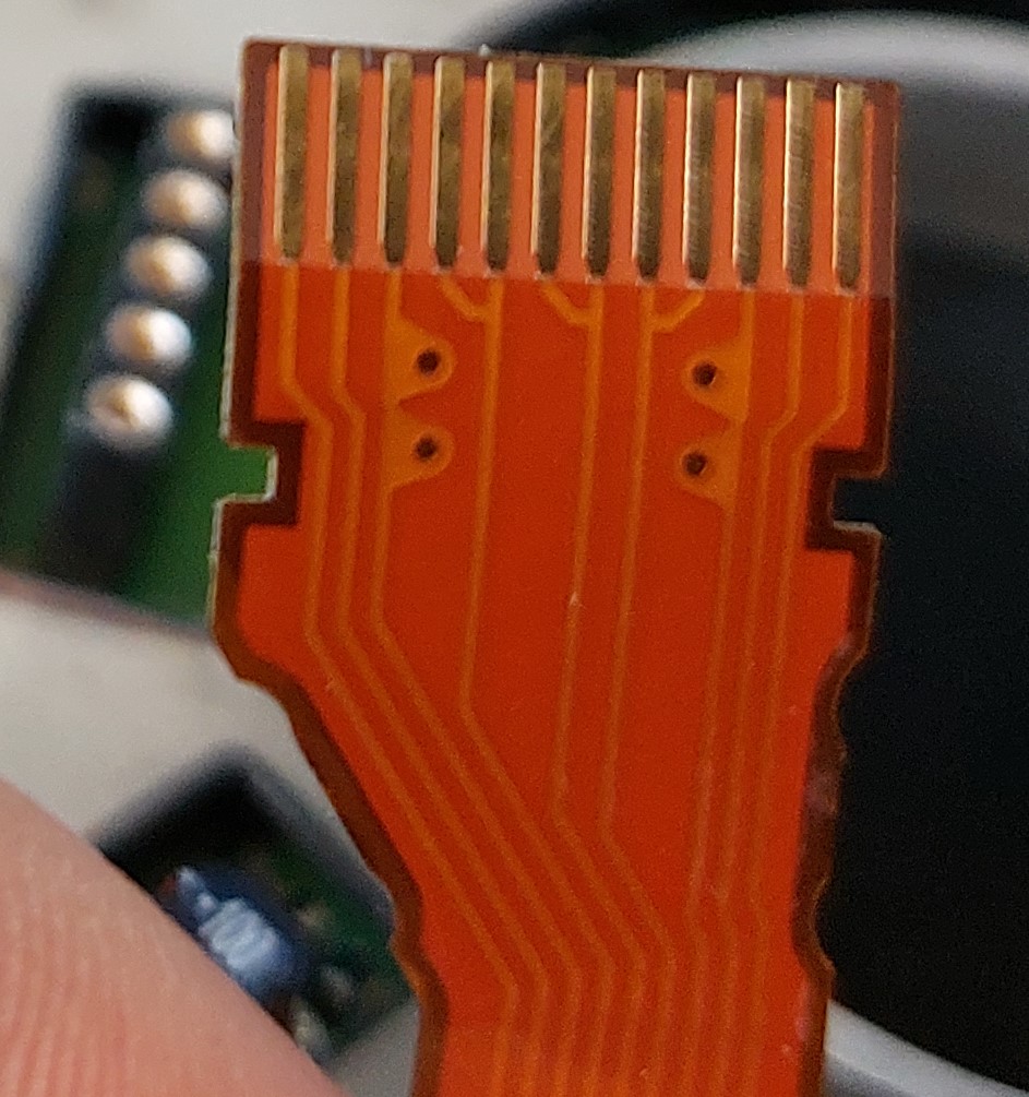
I have a BLDC Motor where a FFC with 9 leads(See picture below) comes out.
I think this is for 3 hall sensors but I am not sure.
My problem is I cant open the motor and need to figure out wich pins is for what.
Does anybody have an idea how I could achiveve that ?
Hello,
you could tell more about the motor, vendor and anything that helps us identify the purpose of the pins. Without knowing Vcc and GND, it’s impossible to test hall sensors.
Those three leads in the middle with 6 connected pins, could as well be an optical encoder with ABI output.
unfortunalty not, the motor is part an assembly with no identifcation number or anything on it.
Is there a way i could test out the leads withouth the risk of damaging the sensor ?
Does this cable also carry the motor phases?
This reminds me of the cables you get with motors on cdrom however they have 11 pins (think they use halls with 4 connectors).
My guess is the middle 3 (i.e the paired ones) are the phases.
If we assume those are the phases. What is the resistance between pair u, v and w? You’d expect the phase to phase resistance to be near identical.
If you have established the phases, you might be able to run it in open loop (ignoring halls).
Let’s say the halls are 3 pin types. Gnd, vcc and output. Your need 5 pins (gnd, h1, h2, h3, vcc) as gnd and vcc are typically shared. So what is the extra pin for? Perhaps it is part of the motor (i.e a star common point).
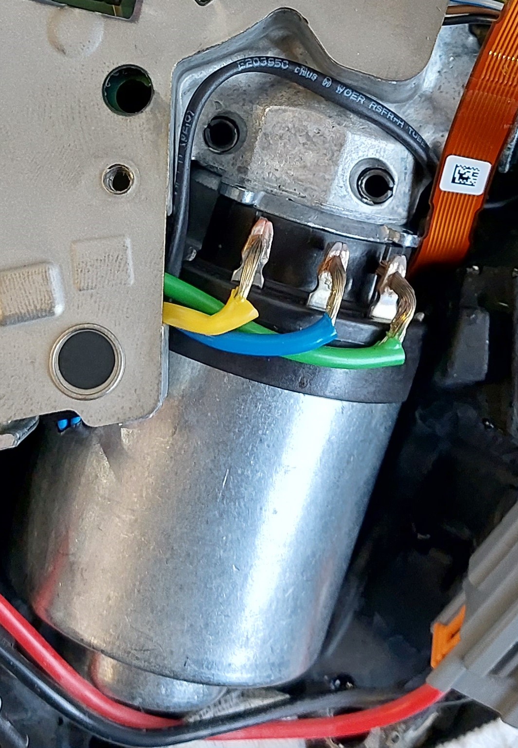
Perhaps you can post a picture of the motor.
No the phases of the motor are seperate
The 3 phases are seperate. I was assuming this motor uses hall sensors because they seem to be quite common.
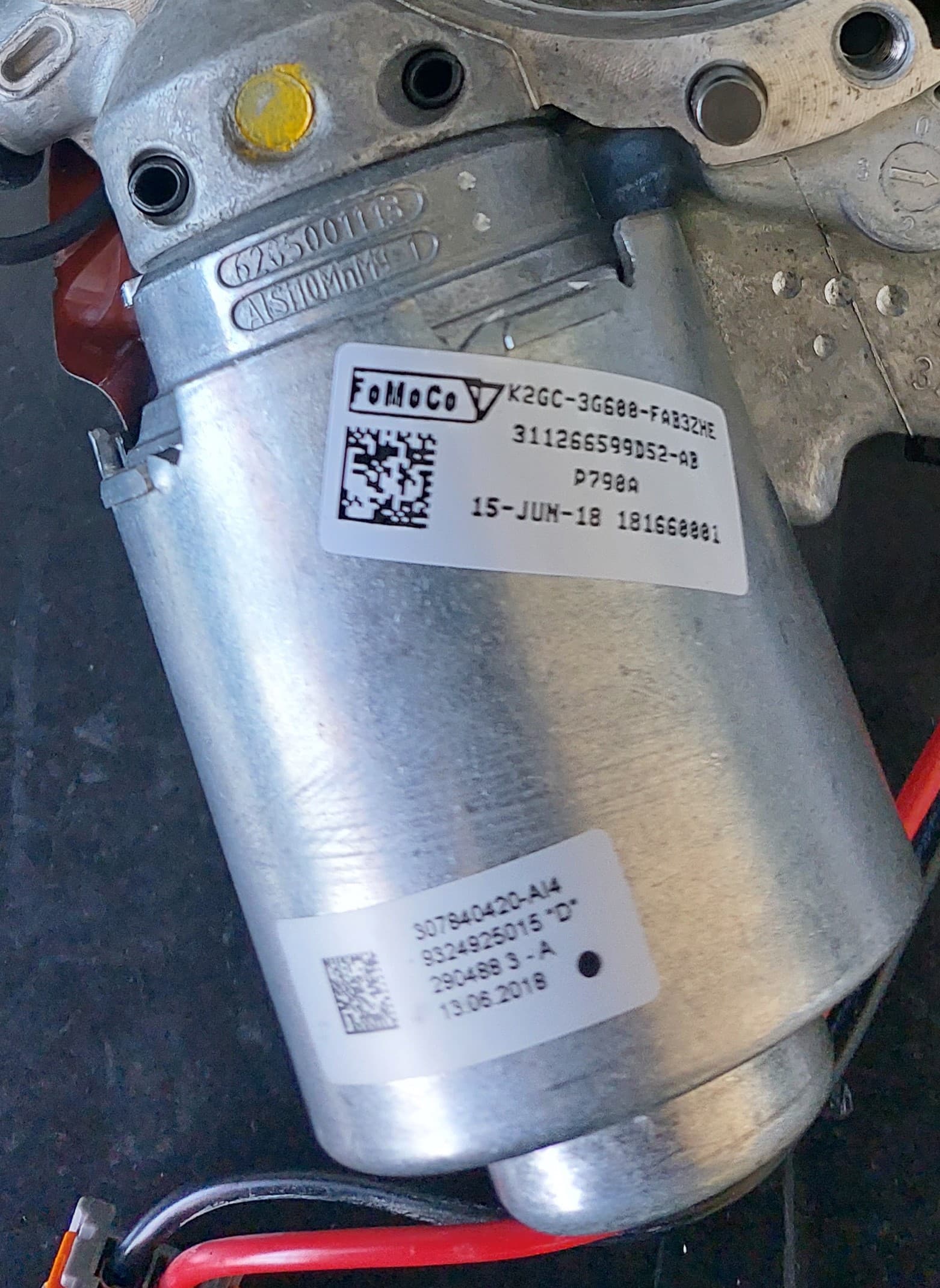
The bottom code 307840420-A14 suggests that it is part of
LINCOLN CONTINENTAL STEERING WHEEL ADDICTIVE ELECTRIC PUMP
https://www.ebay.com/itm/394662931252
Are you trying to salvage an interesting looking motor or do you have a specific use case
This Motor is part of an adaptive steering wheel from ford. I want to reuse that motor and the attached worm gear within a steering wheel for developement and testing.