Hi all.
Here’s my own foc controller design, it’s compatible with vedder’s VESC6, but only jerry bean component (no drv8301), making it much cheaper (<15$ each).
The design is based on CFOCer2, check it also! link here
Design features
Capable of 12s lipo / 50.4v
Continuous current more than 20A (tested), 30A with heatsink (maybe)
3 phase low-side current sensing
type-C usb connecter
Optimized for low cost
Possibility to buy the SMD parts pre-soldered: Everything except MOS and shunt are on one side, and no much special ics.
Separate power stage and control stage, easily replace broken MOS or driver.
The gate driver is time-tested FD6288 (or compatible EG2134), current sensing with standard 4ch universal opamp. (useful information:Link here)
For now I have only test it with VESC firmware, but I guess simple foc lib will work fine aswell.
More test result will release later.
Design resource:link
Just check the corrupted video above, saved it as 7z format and there you go.
Everything is design with EasyEDA (AKA. LCEDA), feel free to modify everything to meet your need.
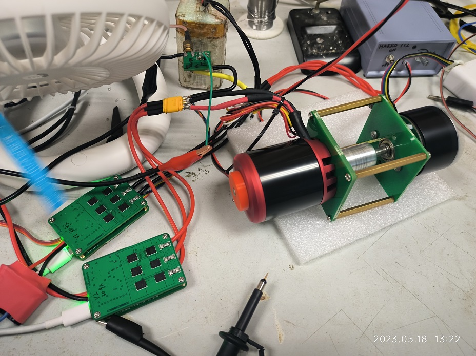
Some bench tests are done today.
I’m using 2 motors, one as motor working in consant speed mode and the other as generator. In this way easy and safe high power testing can bedone.
While driver motor current is around 20A, with some air flow, the MOS temp is finally around 50 degree (right side). The results of the temperature gun test are consistent with the controller report
Ignore left side temperature display, for its temp sensing pin is floating (a mistake).
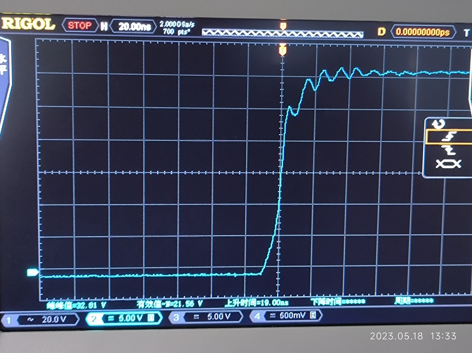
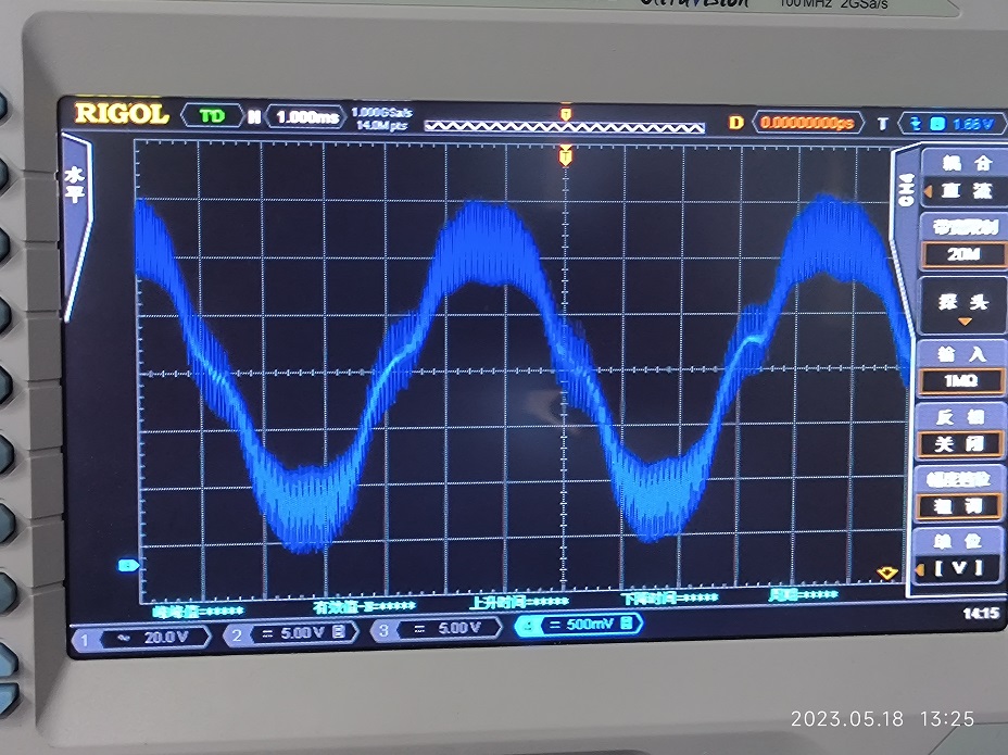
In sums it works fine, doing FOC with no trouble, the results of automatic measurement and manual measurement of motor parameters are very close. It’s fair to say that the hardware design worked as expected.
This is awesome. I didn’t realize VESC was compatible with other boards, I thought it was just for the one board you can buy from them. How complete is this though? Working in one narrow circumstance is one thing.
Yeah, VESC is a great project. Hardware and software were open source for a long time, I think maybe the software isn’t any more for the current VESC versions.
Since its based on STM32 you can actually run SimpleFOC on the open VESC hardware, and if you make a compatible hardware design you can also run the VESC code and VESC tools on your compatible board.
@hbozyq these look like great results - thanks again for sharing them
Do you have a link to the schematic that you have used to design the hardware that is compatible with VESC6? Do you know if there is any tutorial that explains how to compile and load the VESC6 code?
edit some line for the hardware:
line 24, change the name to distinguish it from the original version: #define HW_NAME "PingFOCer"
line 113&115. change the gain: #define CURRENT_AMP_GAIN 33
line 119, shunt resistor in ohm: #define CURRENT_SHUNT_RES 0.001
line 272 to 281, max current should be 3.3V/33/2/0.001ohm=50amp, so with some margin, it should be like :
#ifndef MCCONF_L_CURRENT_MAX
#define MCCONF_L_CURRENT_MAX             35.0   // Current limit in Amperes (Upper)
#endif

#ifndef MCCONF_L_CURRENT_MIN
#define MCCONF_L_CURRENT_MIN            -35.0   // Current limit in Amperes (Lower)
#endif

#ifndef MCCONF_L_MAX_ABS_CURRENT
#define MCCONF_L_MAX_ABS_CURRENT		45.0	// The maximum absolute current above which a fault is generated
#endif
And you are done! Just make it and flash it: make Cheap_FOCer_2_v09
Your design is really good. Exactly as I dreamed. There are a few questions I want to ask.
I looked at your PingFOCerLite design and in that design, instead of doing current sensing with a quad opamp, you used a current sensing amplifier such as INA240 for each channel.
Is there much difference in terms of performance?
Does Quad OpAmp work well?