Hi guys!
I need help to tune PID values for my configuration 
I would like to use Position Control but, to do that, I need first to properly tweak the Velocity PID controller, since it is the inner loop of Position control mode:
My setup is based on Arduino Nano + TI Motor Driver DRV8305 + T-Motor 4004 + AS5047D Magnetic Encoder & SimpleFOC @2.1. Eventually, I will upgrade the MCU with a more poweful board:
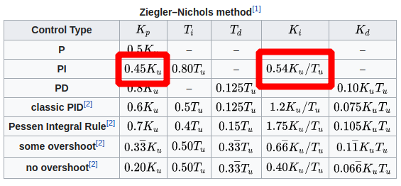
I employed the heuristic Ziegler–Nichols method for Velocity Controller as follow:
- Set all PID values to zero (even the filter).
- Increasing P gain value until the output of the control loop has stable and consistent oscillations. In my case Pu = 0.19.
- Compute the period of these oscillations. As a result Tu=3ms
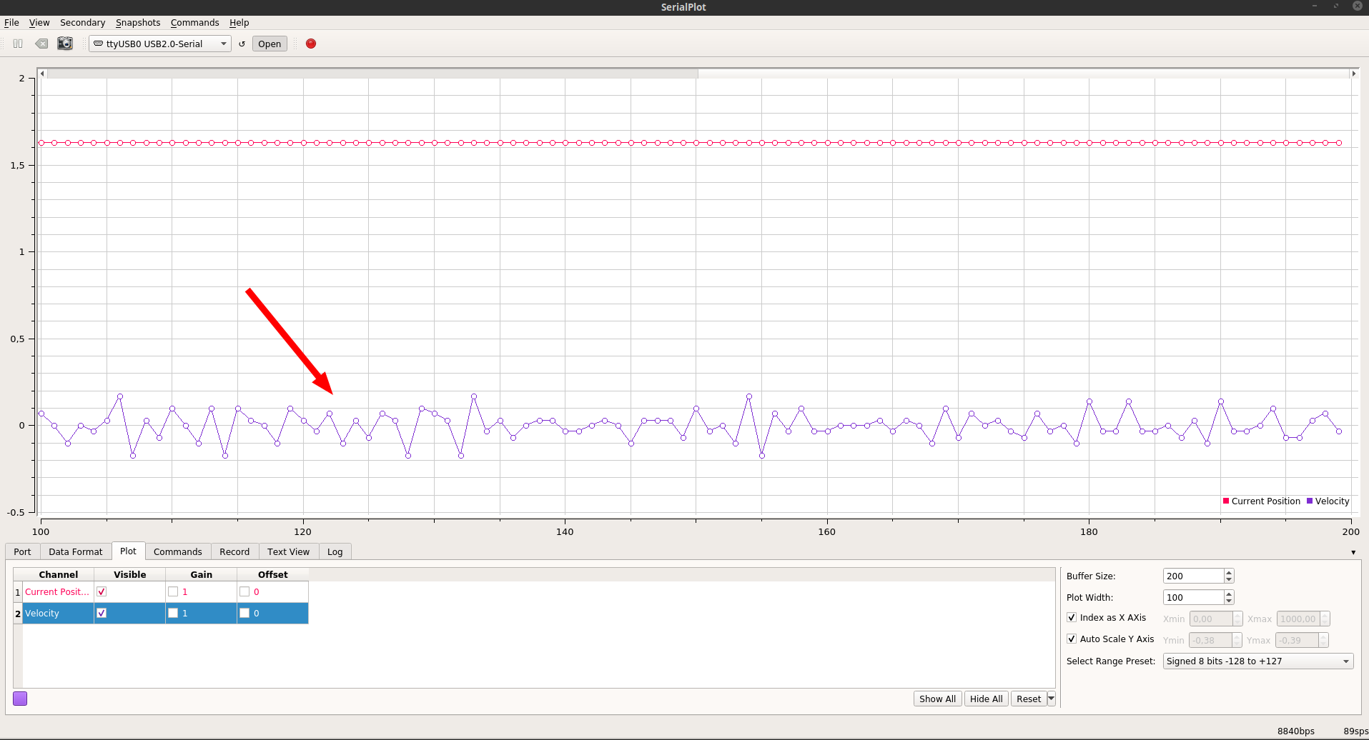
Here the output from the serial and my calculation:
Now, using the Ziegler-Nichols table, I can get the proper values for P and I gains (at the moment, I don’t want to use D gain):
It turns out:


motor.PID_velocity.P = 0.08;
motor.PID_velocity.I = 34.2;
motor.PID_velocity.D = 0;

motor.LPF_velocity.Tf = 0.00;
However, using these two values and set the velocity to a certain value, i.e. 10 rad/s, the motor starts wobbling while spinning.
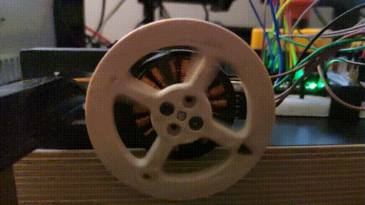
Here the video in slow motion with target velocity = 10 rad/s
Where do you think is the problem in my setup? How can I get sorted?
I also tried to tweak the Tf value, but it didn’t help me much.
Thanks in advance for your help!
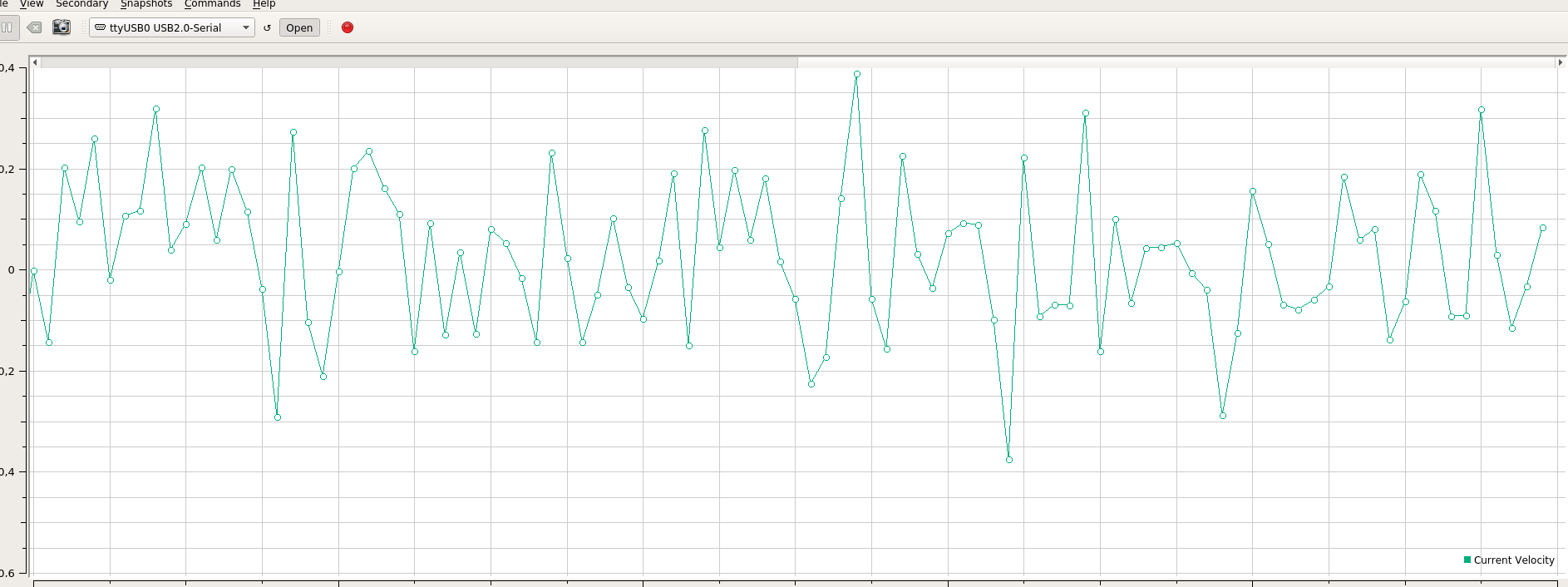
I also checked the output from the encoder, no motor controller at all.
At a steady motor position, the velocity varies from around 0.1 to -0.1:
Is this velocity instability from encoders that might cause the aforementioned tuning to fail?
Hey @well1010,
Man, if it wasn’t for this post I would have forgotten my control lectures and the existence of Ziegler-Nichols!
I think you’re onto a good track and you might one of the few that tune in the non-experimental way (the way I do almost all tuning haha).
I’ve seen this wobbling behavior when the magnet of the magnetic encoder was a bit too far from the sensor. Can you share how are you mounting the magnet to the motor and how for is it to the sensor? Also the tf value should help dampen those spikes in velocity.
Hey @well1010,
Nice to see someone doing some control here!
You have a really nice setup, I am sure you’ll have some good results in no time.
Zieler-Nichols method even though very well known in the industry and one of the first methods we learn for PID parameter choosing is not really intended for smooth operation or for great performance. It is a standardized method intended mostly for the industry where there is no time to spend too much time on tuning the PIDs for industrial drives and it is so simple that is sometimes used as automatic method for finding the parameters.
But it has the down sides as well, it does not guarantee much more than stability of the system 
In practice it is not that useful, especially in cases when you need a very nice smooth operation.
In terms of your results, I’d say that oscillations of 3ms are a bit too short. In Ziegler-Nichols method I’d expect you to have the oscillations that are closer to the mechanical time constant of the motor in the area of >50ms. I am not sure but that would be my guess
Also, your Arduino Nano will not be able to do the execute the loop funciton much faster than 1-2 ms.
Another question, which communication protocol are you using with the AS5047?
In any case, if you do not need to use the Ziegler-Nichols I’d advise you not to use it. I’d advise you to tune the motor in this order:
- All pid values set to 0
- Raise the
PID_velocity.P until your motor starts to follow the velocity set point
- Make sure that you do not have any noise due to the noisy sensor data, if you hear some high pitched noise augment the
LPF_velocity.Tf value (I’d expect a good value to be around 0.005-0.01 s)
- Add a bit of ingral gain
PID_velocity.I until your motor starts following withot any error (I’d expect it to be around 1-30)
When raising the integral gain sometimes you’ll need to raise the proportional gain as well due to their dependency.
- Finally when you have a nice following and a good disturbance resistance of your motor, try changing the target velocity. If once when you change it you have a bit of oscialtions you need to augment the derivation gain
PID_velocity.D (I’d not expect it to be higher than 0.005, you can start with 0.0001)
After all this you should have a nice and smooth motor behavior
Thanks a lot for your answers.
@David_Gonzalez Since you pointed out the encoder distance, you made you think about this important aspect.
Indeed, I realized that my encoder AS5047 is too close to the diametric magnet. Furthermore, some images about my 3D motor mount (from Fusion 360):
I created plastic support that fit the motor shaft and the other side set in place the magnet. However, It seems that the magnet is underneath the encoder without an air gap, thus not respecting the space suggested from the datasheet:
I will try to design again the motor mount support. Perhaps, I will get less noise from the encoder 
@Antun_Skuric Thanks for the detailed description of the steps to take. On my previous occasion to tune PID gains, I took advantage of the Ziegler-Nichols method with positive feedback. Perhaps, I was just lucky enough and don’t get the downsides 
Moreover, I use the AS5047 with SPI communication protocol.
As soon as I will have better motor support, I will employ your strategy as well. Hopefully, I will achieve smooth results 
I tried to fine-tune the velocity PID controller, and it seems to be working now.
In particular, I set these values:
    motor.PID_velocity.P = 0.10;
    motor.PID_velocity.I = 1;
    motor.PID_velocity.D = 0;
    motor.LPF_velocity.Tf = 0.003;
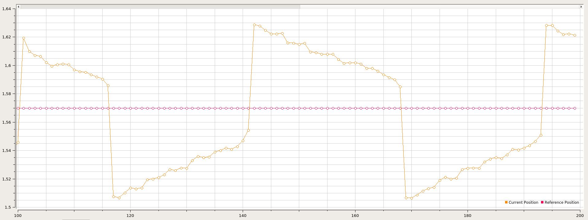
The successive step that I did was to fine-tune the position PID controller. In particular, I would like to achieve stiff motor, thus I need to set high P gain.
The values that I tried with are the following:
motor.P_angle.P = 6.5;
However, the motor keeps moving back and forth at a very infinitesimal angle:

I need to reduce up to motor.P_angle.P = 0.5 to don’t experience that annoying issue. But of course, is not what I would like to get.
Moreover, as I have already pointed out in my previous comment, even though the motor is in a steady position, the current velocity from the encoder looks like the bottom image:
Lastly, I 3D printed new motor support, so now the distance between the encoder and the magnet should be correct.
Any thought about the two aforesaid problems? 
Have you tried removing the I term on velocity PID. I have a feeling you can get away with it being zero (or tiny) in position mode. Alternatively you could try reducing the limit of velocity pid to stop that integral wind up.
The velocity doesn’t look too bad. You could change Tf to 0.01 to smooth a bit more.
Contrary to @Owen_Williams’s suggestion  I would increase the I value of the velocity loop to 3 - 5. Whenever I experience such a behavior ramping this value usually get’s rid of the issue.
I tried both solutions: I cannot totally get rid of the I term since otherwise, I will not have compensation error if I move by hand.
The greater the I, the faster I experience the ramping problem.
I = 0.3
I = 3
I = 5
Moreover, I also increased the filter (it was 0.003):
motor.LPF_velocity.Tf = 0.01
Could it be something related to the velocity noise from the encoder? Do you experience the same behavior?
Try to increase the I even more, I’ve seen what you have on my set-up. With a big enough I the oscillations stop. My guess it has to do with cogging torque or you’re using too low of a voltage limit.
I tried to increase a bit the voltage limit, from 2V to 4V and the motor seems to behave a bit better but the ramping problem is still present. However, I cannot increase the I gain any further since it becomes unstable.
Moreover, since the velocity encoder values are a bit noisy, might it be that this noise affects the full control loop?
How does the velocity encoder values look like in your case? Is it normal to have those spikes?
I use AS5047D encoder with SPI.
I tried both @Owen_Williams and @David_Gonzalez solutions but didn’t get much improvement. For this reason, I suspected that the velocity encoder’s values somehow influence the PID.
For the avoidance of any doubts, this is the code:
#include <SimpleFOC.h>

#define   INH_A 3
#define   INH_B 5
#define   INH_C 6
#define   enGate 2   //Chip Enable

#define   cs 10       //Chip-select
#define   cs_en 7

#define   nFault 8    //Fault reading

//#######_USER VARIABLES_#######
byte pp = 12;                  //BLDC motor number of pole pairs
float phaseRes = 0.452;       //Phase winding resistance [ohms]
uint8_t sourceVoltage = 24;      //Voltage of your power source [Volts]
float maxCurrent = 6;          //Rough approximation of max current [Amps]

//#######_CONTROLLER PARAMETERS_#######
float kvp = 0.07;             //Velocity control loop PROPORTIONAL gain value
float kvi = 1.5;               //Velocity control loop INTEGRAL gain value
float lpFilter = 0.01;
float kp = 6.5;                //Position control loop PROPORTIONAL gain value
float voltageLimit = phaseRes*maxCurrent;
float velocityLimit = 50;   //Velocity limit [rpm]

// motor instance
BLDCMotor motor = BLDCMotor(pp);

// BLDC driver instance
BLDCDriver3PWM driver = BLDCDriver3PWM(INH_A, INH_B, INH_C, enGate);

MagneticSensorSPI encoder = MagneticSensorSPI(AS5147_SPI, cs_en);

Commander commander = Commander(Serial);

void drv_init()
{
...
}

//Fault status and manager for the DRV8305
//Datahseet pages 37 and 38
void faultStatus(){
...
}

void setup() {
    Serial.begin(115200);

    // Pinmodes
    pinMode(nFault, INPUT);
    pinMode(enGate, OUTPUT);
    digitalWrite(enGate, LOW);

    //SPI start up
    pinMode(cs, OUTPUT);
    digitalWrite(cs, HIGH);
    SPI.begin();
    SPI.setBitOrder(MSBFIRST);
    SPI.setDataMode(SPI_MODE1);

    //Motor driver initialization
    delay(250);
//    Serial.println("DRV8305 INIT");
    drv_init();
    delay(500);

    digitalWrite(enGate, HIGH);
    delay(500);

    //Initialise magnetic sensor hardware
    encoder.init();
    //Link the motor to the sensor
    motor.linkSensor(&encoder);

    // driver config, power supply voltage [V]
    driver.voltage_power_supply = sourceVoltage;
    driver.init();
    motor.linkDriver(&driver);

    // set FOC loop to be used: ControlType::voltage, velocity, angle
    motor.controller = MotionControlType::angle;

    // velocity PI controller parameters
    motor.PID_velocity.P = kvp;
    motor.PID_velocity.I = kvi;
    motor.PID_velocity.D = 0; //0.001

    // velocity low pass filtering time constant
    // the lower the less filtered
    motor.LPF_velocity.Tf = lpFilter; // 10 ms smooth

    // angle P controller
    motor.P_angle.P = kp;
    motor.P_angle.I = 0;  // usually only P controller is enough
    motor.P_angle.D = 0;  // usually only P controller is enough

    // maximal voltage to be set to the motor
    motor.voltage_limit = voltageLimit;    // [V]
    // maximal velocity of the position control
    motor.velocity_limit = velocityLimit;  // [rad/s]

    motor.useMonitoring(Serial);

    // initialize motor
    motor.init();
    // align sensor and start FOC
    //motor.initFOC(1.31, Direction::CW);
    motor.initFOC();

    commander.add('M',onMotor,"my motor");

    _delay(1000);
}


void loop() {

    // iterative setting FOC phase voltage
    motor.loopFOC();

    motor.move();

    motor.monitor();

    commander.run();

    // Fault check each 1000 loop calls
    if(downscale_fault_check++ > 1000){
        faultStatus();
        downscale_fault_check= 0;
    }
}
Do you suggest checking something else? Something on the motor? Encoder? Arduino Nano is not powerful enough?
How long does a loop take to run? Nano/uno can manage a loop every ~1ms. Anything slower than this will be harder to tune.
Stm32 and esp32 in my experience have a loop of 100-400us. Faster mcu will be easier to tune.
Does removing motor.monitor() help things?