I have reached the dead lock of phase current measurement issue, i am running in the open loop voltage mode and if i check the CAN data of the phase currents i get the following
I really don’t understand how to debug and find the root cause of the phase current spikes. The Y axis is in amps and the X axis the samples every 5ms.
but -60A? wouldn’t that tend to make the spike towards 0?
Is it possible this is caused by a division by 0 error or something like this? Where the result is -Inf or NaN? Or is even maybe not caused by the driver but by CAN communication problems or something like that?
Other than the spikes I have to say that this looks like very nice current waveforms!
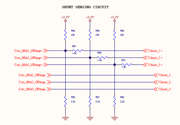
Is the current sensing circuit with micro controller internal op amp gain is 16. The voltage with 0 amps is
0.138* 16 = 2.208 Volts, so the positive current will be towards 3.3V and negative current is towards 0V.
The program calculates everything in terms of signed integer 16 bit, the spikes correspond to value of -30000 with -32767 being the 0V i have converted into Amperes.
Then I agree with candas that you’re getting some 0-readings on the ADC input… perhaps if you sample during the off-time of the MOSFET for some reason.
I wanted to first rectify the spikes issues then go to the gains problem. I will check and increase the ADC sampling point.
But after analyzing the waveform the gray line spikes happens, when its voltage is less than the others or on the negative and its low side pwm will be high for longer time compared to other signals hence its low side MOSFET will be longer for greater period than the others.
But i will try tomorrow by increasing the ADC sampling point.
Is it possible that it can be caused by a noise shunt resistor and due to grounding issues and the signal is not pure and spikes observed on the shunt resistor?
If you have on oscilloscope you can probe those signals to make sure it’s not an electrical issue. My guess is that the MCU is taking too long with the analog read in some occasions and that gives you the spike. What MCU are you using?
The MCU used is STM32G431RBT6 and the phase current sensing is done using interrupt. I will try to toggle a port and see the timing of the ADC interrupt.
The spikes seem to happen only on grey and orange phases, never on blue. Is it chance or is it always like that?
yeah, and it looks like grey has lower amplitude and a small offset… looks indeed like gains and offsets need normalising. This is quite normal and can just be due to small differences in the components.
This is the most complex logic which is tough for me to understand, i have directly taken the ST code did some porting for the high end micro STRB series compared to STCB series and now i am struggling to find the root cause of the issue, the 3 phase current sensing is explained in the below document 3 phase current sensing
the explanation starts from page 52 and he is using injected conversions using Timer4 values.