I have been inspired by previous projects such as the tiny mosquito board by @Valentine to create a mini version (16mm diameter) of my own that can fit on to the back of some tiny 16mm PM1105 motors I have found on aliexpress. I would be immensely grateful if I could get some feedback on the PCB layout/schematic as I don’t have a lot of experience PCB design. The design uses the same MCU as the original Mosquito board but swaps out the driver for a smaller DRV8311 chip that even has current sensing built in. I have also added a mezzanine connector which can be used to break out pins for programming and additional back-pack boards. I’ve put the schematic details and board screenshots below.
The board uses a 4 Layer stack up:
Signal
GND
GND
Signal + GND
Looks pretty good! Can’t go wrong with two unbroken ground planes.
The fault pin in the datasheet says “requires an external pullup to AVDD”, but I’m never sure if they mean it’s required to get a proper reading from the fault pin, or if the chip will refuse to run without it. And without SPI to read the fault status, I think you should connect it to a CPU pin anyway.
You’ll probably need an external electrolytic capacitor on the power input. I don’t know how people decide how much capacitance is needed, but I have some small drone ESCs with 220uF. It would be nice if you could fit ten 22uF 0805 or five 47uF 1206 ceramic capacitors on board.
STM32G031 is rather slow, especially for foc_current mode. And you’ll have to write your own lowside ADC code for it since SimpleFOC doesn’t officially support it. If you can squeeze it in, the 5x5mm G431KBU3 is much better. And I’d recommend an SPI sensor like AS5047 or AS5048 (I can never remember the difference between the two). If you search on this forum, many people start with AS5600 and have trouble with it.
Thanks for your feedback! Thanks for picking up on fault pin, looks like I missed it off when I re-assigned the pins after an initial layout. The reference design for the DRV has it with an electrolytic on the input but I was struggling to find a package that would be small enough, might have to go with your suggestion and fit a few bigger package ceramics on the bottom side of the board. I might try and stick with the G0 MCU for now, just as it is quite a bit cheaper and my main use of the current sensing is to detect a stall for initial calibration as my use case is a micro smart knob.
Yeah, for the low RPM of a knob, G031 and AS5600 should be fine. And if cost is a primary goal, then don't use the 47uF ceramics since they're 22 cents each. With 12V supply, you could possibly even use 16V 22uF 0603 (LCSC part C2762594), but 2x rated is generally recommended. And you probably don't need a full 220uF for those tiny motors, but as said I don't know how to determine the proper capacitance.
I've managed to squeeze in two 22uF 0805 caps close to the power input which I reckon should help, that's pretty much all the space used up now. I'm hoping that because the current requirements for this are so low that I'll be ok. Thanks for your help so far, I'll keep this thread updated when I get the board produced eventually!
Hey there Harry
Wanted to give my two cents on your schematic. I’ve made a few dozen boards using the DRV8311. Mostly just the same board several times trying to fix my mistakes lol. A few things I wanted to point out. I think you have a mistake on the 3.3V supply coming from the DRV8311. The 3.3v regulator will not turn on unless you wake the chip from sleep mode with a logic high signal. In your diagram you’ll power up the 12v supply and then nothing will happen because the drv is still asleep. The stm won’t be able to wake it up since there is no 3.3v supply. I found this one out the hard way…
You might want to break out some UART pins for debugging (TX + RX). Its frustrating not being able to simply read some serial print statements when something isn’t working. The 3.3v regulator is a linear style and therefore not energy efficient. When you drop from 12v down to 3.3v you have to burn off the remaining 8.7v. If your stm + as5600 draw 60ma then the regulator will be burning (8.7*0.06 = 0.5 watts). I used this before and my circuit was overheating. I had to add a heat sink to keep it running. You might consider doing a dedicated 3.3 linear regulator like the ams1117 which can handle more power dissipation. You can also use it to wake the drv from sleep.
Hope this helps.
Those are some great points. Checking the STM32G031 datasheet, its power consumption is much lower than G431, so it probably can be used with linear regulation. I generally budget 35mA for G431 with some peripherals enabled, but G031 is more like 7mA. AS5600 is 6.5mA, so you're only looking at ~14mA, or 120mW of waste heat, which should be fine. A couple of 0402 resistors can make a voltage divider to wake the DRV with very little board space usage.
That’s a great catch, I avoided putting in a dedicated linear regulator to save space but I see now how that might be an issue. It might be worth adding one in for the first prototypes before I can measure the working current draw of the G031 + AS5600. Hopefully I can get away with the voltage divider solution though as board space is already fairly limited.
I reckon I will try and add in a small linear regulator, just remembered that my I want to keep an input voltage range of at least 9-12V, so a voltage divider solution will likely fail. As for the point about the UART - I've broken out the UART2 bus to the mezzanine connector, there is going to be a simple daughter board with the connections broken out for programming/Serial wire debug etc. Eventually I am going to use this connector for interfacing with some additional sensors and peripherals as the end goal is a sort of haptic knob.
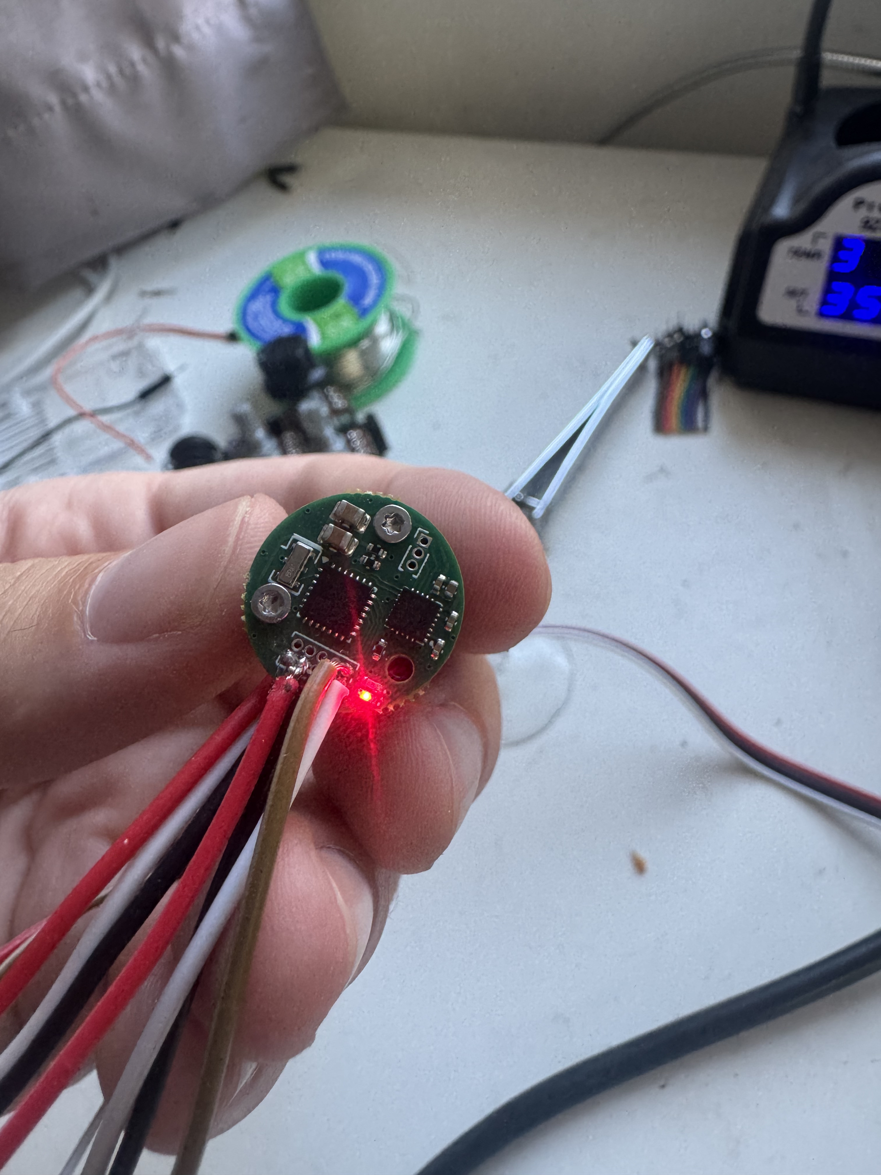
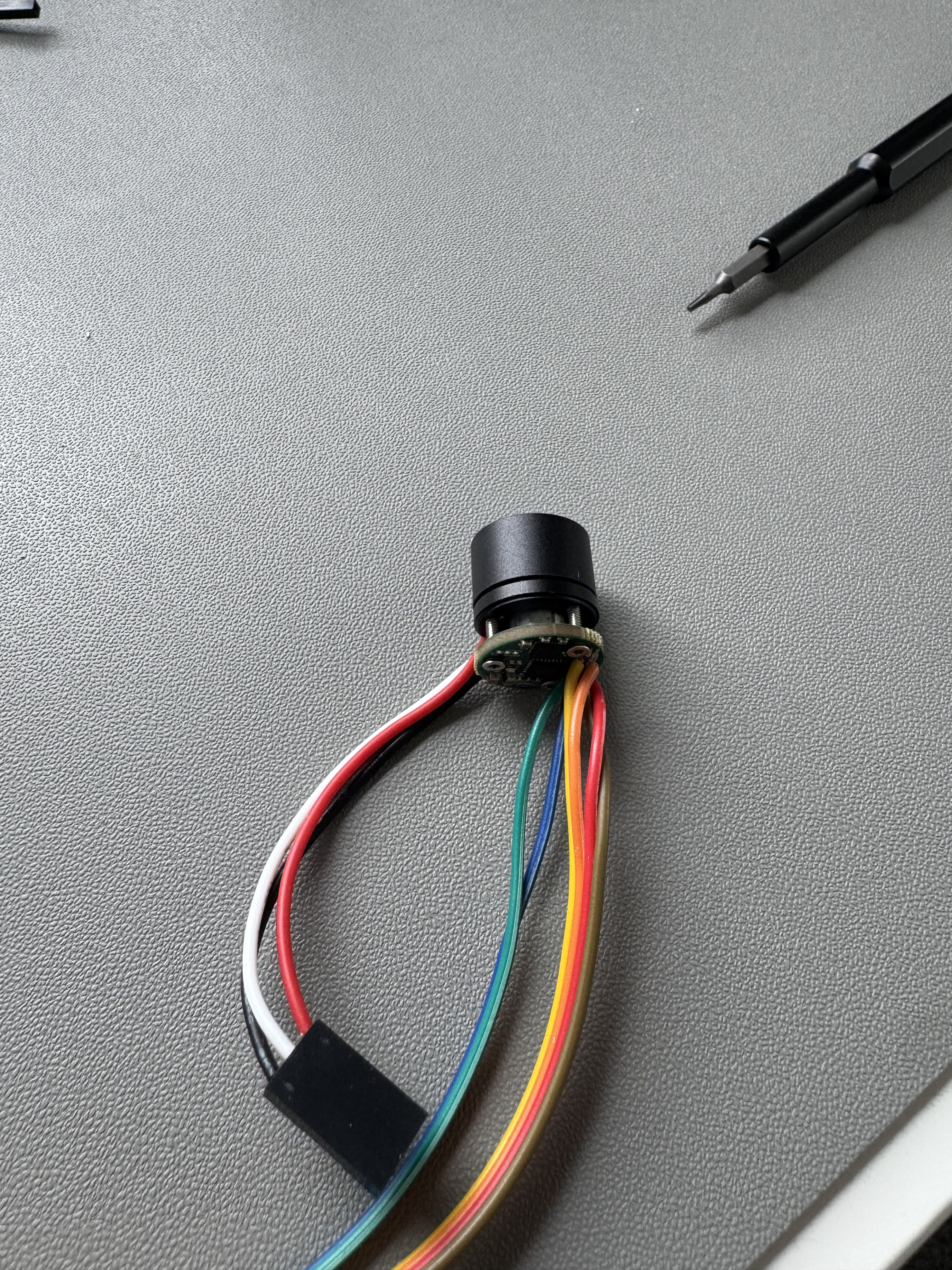
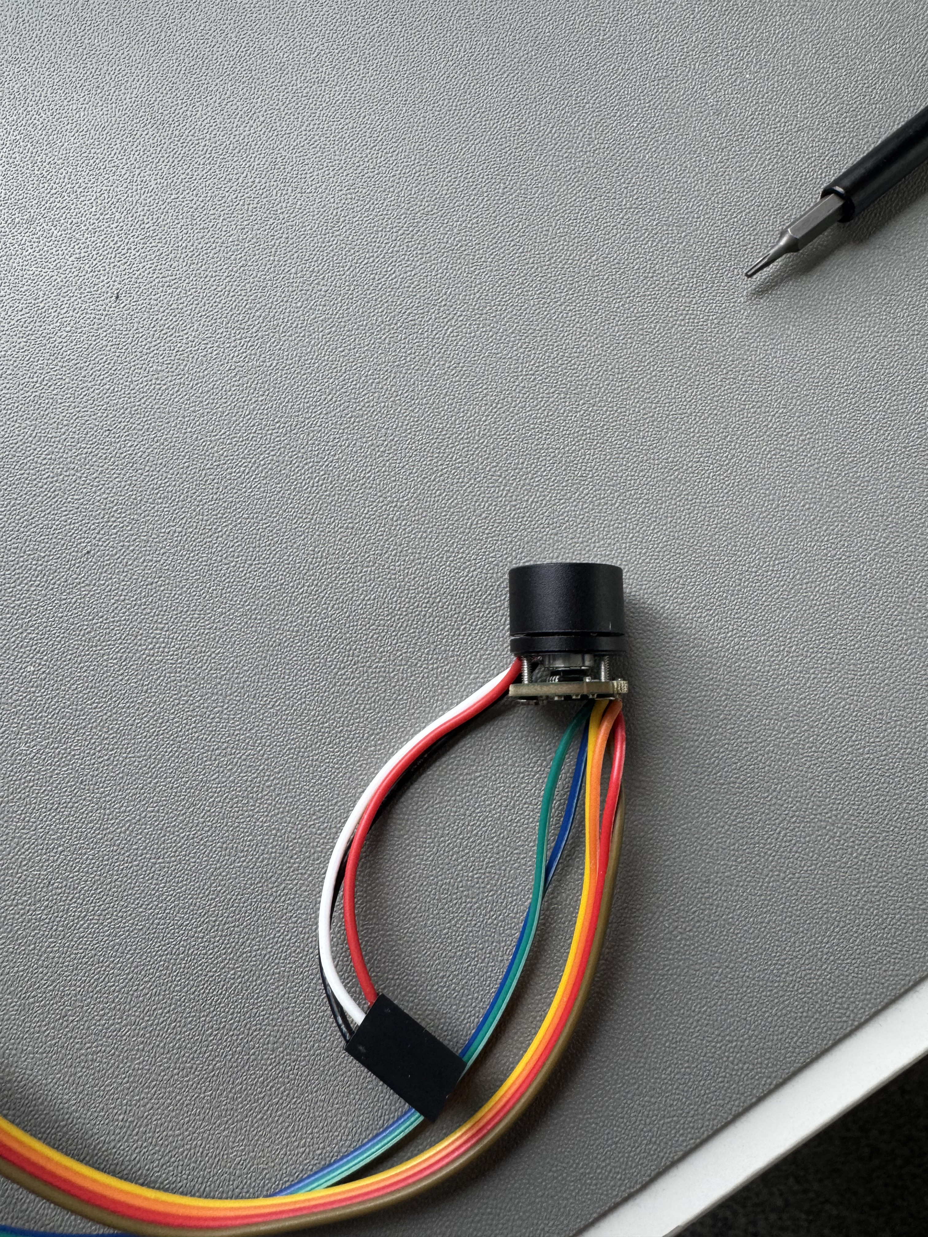
Pleased to say my board design has come out well, everything appears to be working as intended, thanks again to the suggestions above with powering from the DRV8311, it seems to cope fine powering everything from its 3.3v regulator which has helped keep the board size to only 16mm diameter.
Hey, congratulations, that looks like a really nice and very tiny driver
is its design open source? I’m sure people here would be interested…
Hi there, Thanks! I am pretty pleased with it a this is the first PCB I have designed too so pretty shocked it has all worked. I am going to be fixing a couple of issues in the upcoming weeks, e.g adding some proper connectors as soldering on to those 1mm pins has been a bit of a nightmare. I'll probably get round to publishing it when that's done, as I'd say its pretty tricky to use in its current form.
For 1.27mm and finer pitch pins, it's much easier it you warm it up with a heat gun before going at it with the soldering iron. Better still if you can use both at the same time, but I often don't have enough hands.


Thanks for your feedback! Thanks for picking up on fault pin, looks like I missed it off when I re-assigned the pins after an initial layout. The reference design for the DRV has it with an electrolytic on the input but I was struggling to find a package that would be small enough, might have to go with your suggestion and fit a few bigger package ceramics on the bottom side of the board. I might try and stick with the G0 MCU for now, just as it is quite a bit cheaper and my main use of the current sensing is to detect a stall for initial calibration as my use case is a micro smart knob.
– Harry_BrentonYeah, for the low RPM of a knob, G031 and AS5600 should be fine. And if cost is a primary goal, then don't use the 47uF ceramics since they're 22 cents each. With 12V supply, you could possibly even use 16V 22uF 0603 (LCSC part C2762594), but 2x rated is generally recommended. And you probably don't need a full 220uF for those tiny motors, but as said I don't know how to determine the proper capacitance.
– dekutree64I've managed to squeeze in two 22uF 0805 caps close to the power input which I reckon should help, that's pretty much all the space used up now. I'm hoping that because the current requirements for this are so low that I'll be ok. Thanks for your help so far, I'll keep this thread updated when I get the board produced eventually!
– Harry_Brenton