When using an open-loop velocity control with a constant target velocity (with the example code), the motor doesn’t move smoothly and instead jumps in large steps. Any idea what could be causing this issue? I am using a T-Motor GL35 BLDC motor with an Arduino Uno and a V2 simpleFOC shield.
In case it helps, the pole pairs should be correct from the data sheet and the “find pole pairs” example. This example also behaves weirdly after configuring the number of pole pairs, as it doesn’t move as one would expect with a constant voltage and instead just jumps to a position and stops.
Huh… wonder what is going on? Note that by using backticks ( ` )
you can post code
For open loop mode, it should not really matter what number of pole pairs you set, although the speed will be wrong if you use the wrong number.
What speed are you using? A low value like 1 or 2 rad/s is fine for testing.
Can you lower the voltage somewhat. 16V is a lot for such a little motor, and currents will rise to 4.5A or so, which will probably be too much for the SimpleFOCShield. Is the driver getting hot?
One reason for it not working is that its thermal shutdown is kicking in.
If you lower the voltage to 5V or 10V for first tests this will be fine.
If you don’t have a different power supply, you can use the driver.voltage_limit setting to manually set the limit.
I tested speeds between 1 and 5 rad/s and saw the stuttering regardless of speed.
The driver was getting hot, so I limited the driver.voltage_limit to 8V (although the driver and motor would get hot eventually so I’d stop the code and unplug the power supply). I can try just using a lower power supply voltage and not using the limit in the code.
This is the code I was using:
// Open loop motor control example
#include <SimpleFOC.h>


// BLDC motor & driver instance
// BLDCMotor motor = BLDCMotor(pole pair number);
BLDCMotor motor = BLDCMotor(7);
// BLDCDriver3PWM driver = BLDCDriver3PWM(pwmA, pwmB, pwmC, Enable(optional));
BLDCDriver3PWM driver = BLDCDriver3PWM(5, 10, 6, 8);

// Stepper motor & driver instance
//StepperMotor motor = StepperMotor(50);
//StepperDriver4PWM driver = StepperDriver4PWM(9, 5, 10, 6,  8);


//target variable
float target_velocity = 3;

// instantiate the commander
Commander command = Commander(Serial);
void doTarget(char* cmd) { command.scalar(&target_velocity, cmd); }
void doLimit(char* cmd) { command.scalar(&motor.voltage_limit, cmd); }

void setup() {

  // driver config
  // power supply voltage [V]
  driver.voltage_power_supply = 16;
  // limit the maximal dc voltage the driver can set
  // as a protection measure for the low-resistance motors
  // this value is fixed on startup
  driver.voltage_limit = 8;
  driver.init();
  // link the motor and the driver
  motor.linkDriver(&driver);

  // limiting motor movements
  // limit the voltage to be set to the motor
  // start very low for high resistance motors
  // currnet = resistance*voltage, so try to be well under 1Amp
  motor.voltage_limit = 8;   // [V]

  // open loop control config
  motor.controller = MotionControlType::velocity_openloop;

  // init motor hardware
  motor.init();

  // add target command T
  command.add('T', doTarget, "target velocity");
  command.add('L', doLimit, "voltage limit");

  Serial.begin(115200);
  Serial.println("Motor ready!");
  Serial.println("Set target velocity [rad/s]");
  _delay(1000);
}

void loop() {

  // open loop velocity movement
  // using motor.voltage_limit and motor.velocity_limit
  motor.move(target_velocity);

  // user communication
  command.run();
}
Your motor has under 2 ohms of phase resistance (3.5Ohm - phase to phase) which means that at 8V it will produce more than 4Amps of current. https://www.robotshop.com/en/cubemars-gl35-kv100-bldc-gimbal-motor-with-encoder.html
Reduce the voltage limit to 1Volt of so and start from there. You can use the commander to test different values of the voltage limit in real-time.
It is very important to start calibration and test at low voltages and if you have bench supply just set current limiting. I have made a rookie mistake before and overloaded driver resulting in smoke show.
I’d set the supply power at 5V and start from 1V+.
I do have this motor myself and i have tested it with L6234D.
It would make a lot of sense for you guys to post your code here first before we start making assumptions.
I am having the exact same problem. In open loop velocity mode the motor steps 14 times per revolution (It has 7 pole pairs or 14 magnets). It is as if the motor were a stepper motor. The speed and steps are acuurate.
But now I’m wondering if this is a problem. Why should I expect that stepping the phases electronically should result in smooth motion of the motor? OK, maybe if the motor has a lot of momentum but the rotor has very little mass.
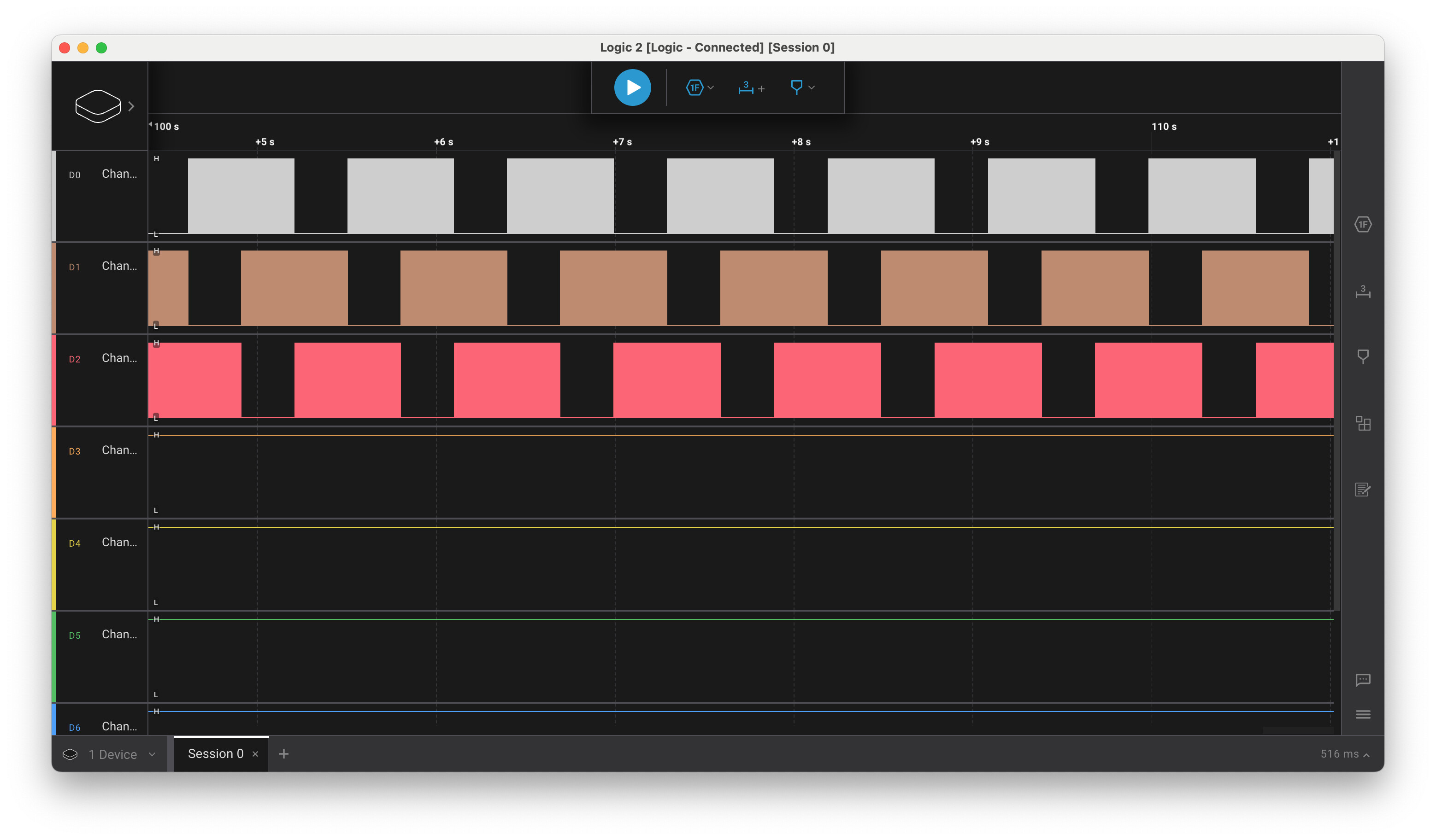
Here is a screenshot from a logic analyser showing the comutation from the ESP32 pins when the target velocity is set to 1 radian per second. (2Pi seconds per revolution) You can see the timing on the pulses. (very roughly 1 second per setp) The pulses look good to me. If you zoom in you can see each block is actualy a series of PWM with very small duty cycle.
This sounds like motor cogging, combined with a voltage that is perhaps a bit low for driving the motor.
The cogging depends on the motors construction, but normally lower pole counts have higher cogging - so a 7PP out runner can be quite “coggy”.
This looks normal. The phases are 120° apart, leading to this pattern, and as you say when you zoom in, you can see the blocks are actually PWM square waves. Within each block you should see the duty cycle increasing and then decreasing again.
Things you can try:
In velocity mode the cogging causes cyclic forces which in turn oppose and support the direction of motion. Depending on the PID settings, and in particular the LPF settings, the velocity PID will pick up these velocity changes, and react to them. It can be pretty hard to tune out this behaviour.
You can see if the velocity is more smooth at constant voltage in torque-voltage mode, then it means the velocity controller is reacting to the cogging. You can increase the LPF time constant to make it smoother, but then it will be less reactive to load changes which can cause other problems, depending on the application.
Increasing the voltage should reduce the effect of cogging .
Often, adding load to the motor will make a big difference - as you observed, the unloaded rotor has low inertia, and therefore the cogging has greater effect.
Check your modulation and voltage limits - if you are over-modulating (motor.voltage_limit > 0.5*driver.voltage_limit) your modulation will not be sine-like. Likewise if your driver.voltage_limit is very much lower than your power_supply_voltage, you may not have great range on the PWM signals, leading to a suboptimal modulation. In this case you could try to change the PSU to bring it closer to the desired voltage.