Hi @marethyu ,
Its actually a lot more complicated than that - motors are inductive loads, and BLDCs are driven by time-varying currents, so the motor has impedance rather than resistance, and there are many other factors at play to determine the current flowing through the motor in a given situation.
But as a “upper bound”, for situations where (for example due to a software failure) the motor windings have DC current applied, this measurement is a very useful indication of the kind of current you could expect worse case.
Both I guess. The phase current is whatever is flowing through the phases. It is limited by
-
the power source (for example LiPo batteries will provide huge currents effectively limited by everything burning/melting, while your desktop PSU will typically just cut out at some current limit)
-
the driver architecture (the L6234 has thermal protection, but looks like it doesn’t have a dedicated over-current protection).
-
the motors characteristics (e.g. impedance, back EMF, etc…)
-
the software driving it
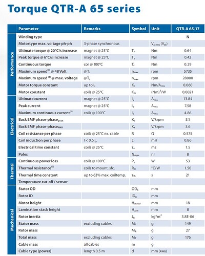
That rating is a maximum value, your data sheet gives different values for “ultimate current” - not sure what they mean by this, “peak current” - what the motor can handle for short periods of time (short as in measured in ms), and “maximum continuous current” - 4.86A, with the motor at 100°C - so that gives you a hint that to go this high will require cooling.
Realistically, running a motor at anything close to its maximum ratings will require careful design of the whole system including cooling, over-temperature protection, etc… like with any engineering, its probably a good a good idea to design things to fit well under the maximum parameters.
Yes, very much so. Because you say you have low loads, you can expect very low currents in closed loop mode, and driver and motor will stay cooler.
Roughly speaking, the software just commands a commutation pattern to the motor, and expects it to follow it. This is very wasteful electrically. By closing the loop the FOC algorithm knows exactly the position of the motor and commands a more optimal commutation pattern for the given situation (load, desired speed, current speed etc…). The difference under low load situations is quite big.
For slow moving type applications, gimbal motors are more suited (higher resistance, higher pole count, lower KVs). But you will probably get it working well - it will require more tuning of the PID parameters, I would assume, because the motor will be a bit more “twitchy”.
How smooth it is, that is often more dependent on the quality of your sensor loop (speed of reading the sensor, speed of FOC control loop) and especially on the motor quality. Some motors have more pronounced cogging than others, some are mechanically unbalanced, and lower pole counts are harder to run smoothly slowly than higher pole counts…
The data sheet says “8 poles” - looks like its an in-runner with 4 pole-pairs then? You’ll have try it out… If you have the option of bringing the power supply voltage down closer to the chosen voltage limit the algorithm will have finer control by better exploiting the available PWM range, which may help things.
