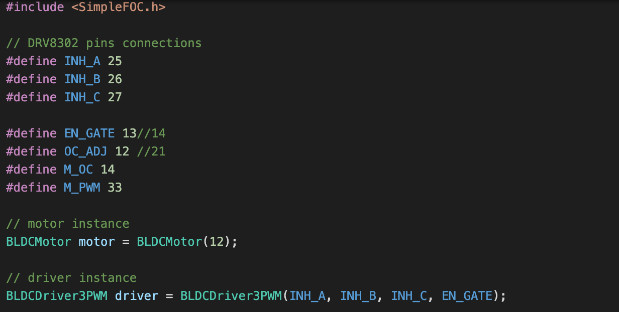
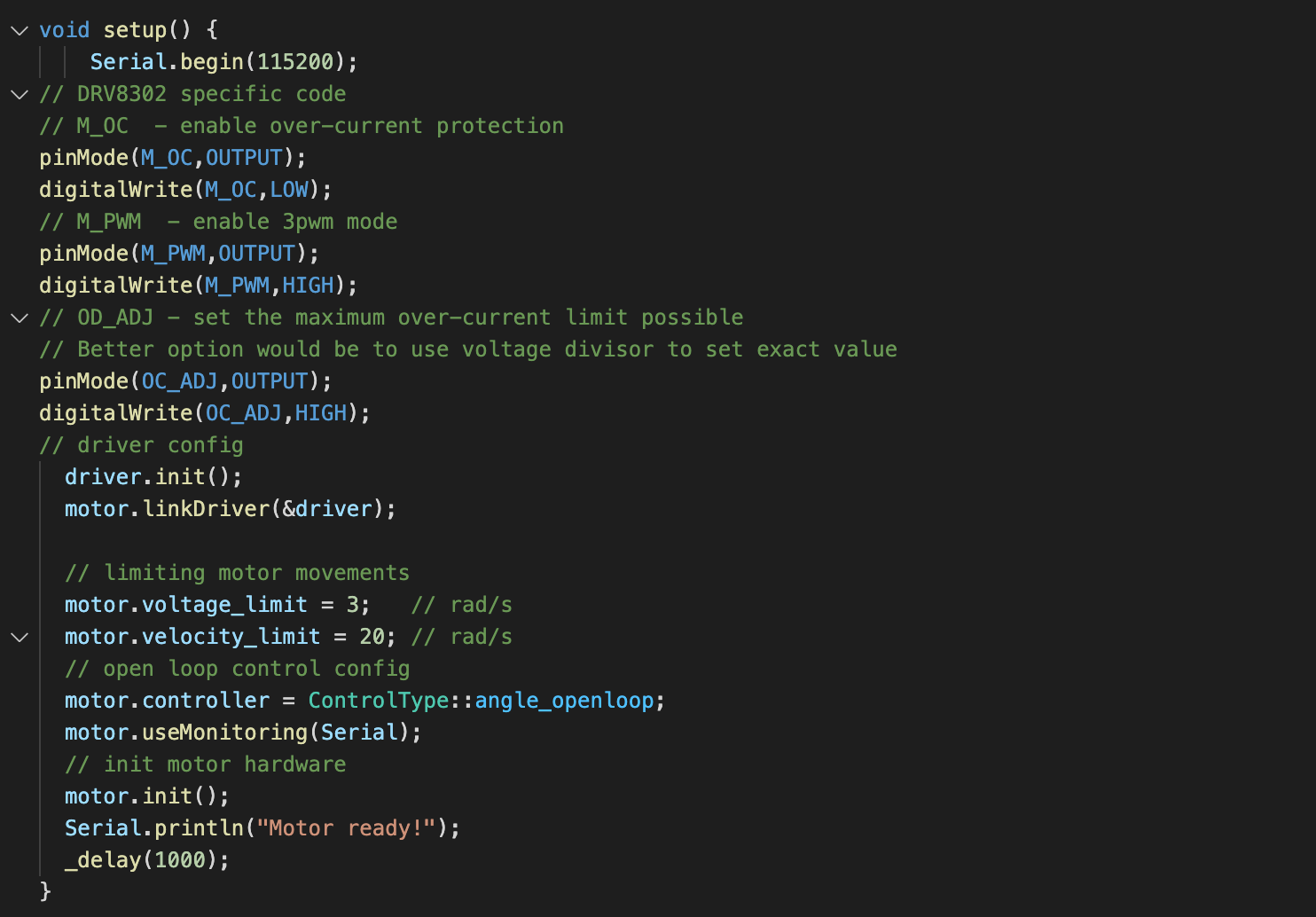
Im trying to run the example code I’ve found to get used to the libraries. but after the motor init a got a fault and the motor keep buzzing, the power supply is limited to 12V and 0.05 A.

12V and 0.05 A for this motor?
I’ve set everything low to test the board first.
Hey @bgvsan,
I would suggest you not to limit the current so low. With 50ma even my big gimbal motors have problems.
I would suggest you to limit the voltage in the code to motor.voltage_limit=0.5 // or maybe 1V and current on your power supply arround 1amp(can be even more).
Also I’d suggest you to first make sure the velocity open loop works. And then angle loop.
What is the led that turns on when this noise happenes?
Is it ovecurrent protection?
Thanks for the reply, I’ve moved to the velocity example, and rised to 1A and 0.5 limit and at least it moves.
the led is the Fault flag.
the angle now seems to work, but I have to keep a value of motor.voltageLimit = 0.5 otherwise the motor is really noisy and stalls.
Hey @bgvsan,
This is normal with low resistance motors. You will have to keep the voltage limit very low in order to prevent the current being very high.
The rule of thumb is that the current will be voltage/resistance so for low resistance you need low voltage to keep the current low.
Did you try to spin your motor with high velocities?
Because of the influence of the back emf for the same voltage the current will fall a bit and you should have less noise.
These kinds of motors are really not intended to be run in this kind of open loop mode. In closed loop mode you will have less problems with high currents.
Thanks for be so exhaustive,
I’ve tried to set 60 rad/sec, I have to increase to 0.9 and provide 2.5A, but really cannot go more than that as it stalls.
But yes, I confirm high rpm goes below 0.5A and runs better.
So my guess was exact and with the closed loop the lib is working better.
Thanks for the support, will be awesome discover and analyze the lib.
Hi, were you able to run the motor correctly? I’m using the same hardware except motor. Are you able to share the code you used? thanks
Hi sorry for the delay at the end I did it. now I’m working on a closed loop with a sensor don’t know if is relevant to you.
1 Like
I have a further question around the same topic. My motor is 12v input with following parameters:

I am creating a cable car. When moved on cable, the motor just stalls in its position. The weight of the car is less than 300gms. Based on n.m to kg.cm it should not stall in its position. Also, when i hold the wheel it does not seem to have much torque so i believe its because of the voltage issue.
Now, based on the above values, should i still pass 1v or 2v for motor voltage? Is it ok to go 12v for the motor voltage? Currently testing with the open loop example below:
// Open loop motor control example
 #include <SimpleFOC.h>


// BLDC motor & driver instance
// BLDCMotor motor = BLDCMotor(pole pair number);
BLDCMotor motor = BLDCMotor(14);
// BLDCDriver3PWM driver = BLDCDriver3PWM(pwmA, pwmB, pwmC, Enable(optional));
BLDCDriver3PWM driver = BLDCDriver3PWM(11, 10, 9, 8);

// Stepper motor & driver instance
//StepperMotor motor = StepperMotor(50);
//StepperDriver4PWM driver = StepperDriver4PWM(11, 10, 10, 6,  8);

//target variable
float target_position = 200;

// instantiate the commander
Commander command = Commander(Serial);
void doTarget(char* cmd) { command.scalar(&target_position, cmd); }
void doLimit(char* cmd) { command.scalar(&motor.voltage_limit, cmd); }
void doVelocity(char* cmd) { command.scalar(&motor.velocity_limit, cmd); }

void setup() {

  // driver config
  // power supply voltage [V]
  driver.voltage_power_supply = 12;
  // limit the maximal dc voltage the driver can set
  // as a protection measure for the low-resistance motors
  // this value is fixed on startup
  driver.voltage_limit = 6;
  driver.init();
  // link the motor and the driver
  motor.linkDriver(&driver);

  // limiting motor movements
  // limit the voltage to be set to the motor
  // start very low for high resistance motors
  // currnet = resistance*voltage, so try to be well under 1Amp
  motor.voltage_limit = 3;   // [V]
  // limit/set the velocity of the transition in between
  // target angles
  motor.velocity_limit = 10; // [rad/s] cca 50rpm
  // open loop control config
  motor.controller = MotionControlType::angle_openloop;

  // init motor hardware
  motor.init();

  // add target command T
  command.add('T', doTarget, "target angle");
  command.add('L', doLimit, "voltage limit");
  command.add('V', doLimit, "movement velocity");

  Serial.begin(115200);
  Serial.println("Motor ready!");
  Serial.println("Set target position [rad]");
  _delay(1000);
}

void loop() {
  // open  loop angle movements
  // using motor.voltage_limit and motor.velocity_limit
  motor.move(target_position);

  // user communication
  command.run();
}
Also, one more question i had was around my understanding about " driver.voltage_limit = 6;"
As per my understanding, if this limit is set to 6, then max power supplied to the motor would be 6v regardless of what i set for motor voltage. Correct?
That is correct, from a software point of view. If you set driver.voltage_power_supply correctly, then the software limit of 6V should translate into 6V limit on the output side.
The driver limit acts as an absolute limit, after the the motor limit.
But if you set the motor limit too high compared to the driver limit, then the output signal will be “clipped”, by the driver limit. You can picture this like the sine-waves being “cut off”, with flat tops.
1-2V is quite low for a 10Ω motor… You can probably go as high as 5-6V without exceeding its 790mA current rating.
But as long as you are running open loop mode, I would be quite careful, and often touch the motor and check the current on the power supply (if you can). Even at 500mA, if you leave it running for a number of minutes the motor will get very hot. If you’re not careful you will damage the motor.
Thanks @runger
Your answer helped me learn what to look for in setting this voltage so big thank you. just to understand it a bit more… if I were to use the motor 4315 with 15.2 for resistance and 0.59 for nominal voltage, what voltage limit will apply?
Also, as per the datasheet, stall current is 1.2 for 4310 and 0.9 for 4315 so I guess it is safe to use any driver with almost twice (2amp) current, right? Besides, since the SimpleFOC lets us set driver voltage limit, is it ok to use a motor with higher stall current and simply restrict its power draw at the driver?
P.S: going to run them in closed loop with magnetic sensor
hi, sorry, I missed this one… in answer to your questions:
Yes, that should work out fine.
Yes, in general this is true. In practice, if you actually stall the motor, you will still have to pay attention to the situation, because even limited to only 1A current a motor can get very hot and “burn up” if it is stalled and you just keep powering it for a long time.
For a high resistance motor like the one you suggest, this will be the main problem.
@runger thank you for your detailed replies. Its very helpful to me.
So, restricting the voltage and amps at the software level and then for an additional measure what monitoring methods can we implement to say in real time that if current goes above certain level for a certain amount of time then change the motor status to “ME0” - disable it.
Hi @runger, I am confused a bit here on these parameters. If my motor is 16v nominal with 0.79amp, shouldn’t I be able to supply it 16v or at least 12v? The reason I ask this is that the motor is sluggish at even 8v, it starts to show some strength at 9v and higher. Now that I am running it with the AS5047 encoder, hope higher voltage is ok.
Basically i want to understand why we set lower voltage in SimpleFOC as compared to the nominal voltage for that motor.
(sorry, similar question i have asked on another post. But it seemed so relevant here as well. Don’t hate me please )
Yes, exactly!
Yes. Think of it like this: the motor when moving and under commutation is complicated - more like AC than DC, and the motor’s inductances, the back-EMF caused by the physical magnets in the windings and other factors come into play.
So usually the (RMS) current in this situation will be lower than if you just connected DC power to the motor.
So looking at the DC situation is like an upper bound approximation or worst case scenario - what would happen if a software failure left the driver switched on permanently conducting through the motor.
So for the motor you mentioned, with 15.2Ohm resistance, in a DC situation with 16V you would get 16/15.2=1.05A of current.
So in this way you can choose an initial limit for your tests that should be safe.
Ideally you can set up an amp-meter or use a PSU which displays the output current. Then you can run the motor, tune your PIDs or other settings, and check the real current consumption under load, etc.
If it looks good, you can raise the limit.
Thank you @runger - I get it now regarding the voltage setup. We are setting everything with upper limit in mind to protect the motor and the board and it makes sense.
Is there any easy way to query the current or set a monitoring limit that would trigger a response regarding current being so high?
If the hardware has current sensing circuitry, then you can measure and react to the currents. If not, you can configure the motor’s phase resistance and the software will estimate the current, but it’s not really suitable for implementing protection…
Got it. So, get the hardware part solid and not rely entirely on software-based estimation.