Hi all,
I got my o-drive connected to Arduino IDE and now I’m trying to run my motor, rv-120-sh on open loop velocity control mode as I would any motor for the initial testing but, I see that the motor wont budge. Can i get your guys opinion on the voltage settings and anything else for that matter.
ps:I’m using a 48v battery pack and I used this o-drive example as reference for pinouts.
On a side note I also tested out the hall sensors connected to the motor individually which happened to work with no problem.
here is the code I tried out
#include <SimpleFOC.h>

// Odrive M0 motor pinout
#define M0_INH_A PA8
#define M0_INH_B PA9
#define M0_INH_C PA10
#define M0_INL_A PB13
#define M0_INL_B PB14
#define M0_INL_C PB15
// M0 currnets
#define M0_IB PC0
#define M0_IC PC1
// Odrive M0 encoder pinout
#define M0_ENC_A PB4
#define M0_ENC_B PB5
#define M0_ENC_Z PC9


// Odrive M1 motor pinout
#define M1_INH_A PC6
#define M1_INH_B PC7
#define M1_INH_C PC8
#define M1_INL_A PA7
#define M1_INL_B PB0
#define M1_INL_C PB1
// M1 currnets
#define M1_IB PC2
#define M1_IC PC3
// Odrive M1 encoder pinout
#define M1_ENC_A PB6
#define M1_ENC_B PB7
#define M1_ENC_Z PC15

// M1 & M2 common enable pin
#define EN_GATE PB12


// Motor instance
BLDCMotor motor = BLDCMotor(14);
BLDCDriver6PWM driver = BLDCDriver6PWM(M0_INH_A,M0_INL_A, M0_INH_B,M0_INL_B, M0_INH_C,M0_INL_C, EN_GATE);


float target_velocity = 0;  // [rad/s]

Commander command = Commander(Serial);
void doTarget(char* cmd) {
  command.scalar(&target_velocity, cmd);
}
void doLimit(char* cmd) {
  command.scalar(&motor.voltage_limit, cmd);
}

void setup(){
 /////////////////////////////////////////serialMonitor_setup////////////////////////////////////////////
  Serial.begin(115200);

  /////////////////////////////////////////driver_setup///////////////////////////////////////////////////
  // pwm frequency to be used [Hz]
  driver.pwm_frequency = 20000;
  // power supply voltage [V]
  driver.voltage_power_supply = 48;
  // Max DC voltage allowed - default voltage_power_supply
  driver.voltage_limit = 35;
  // driver init
  driver.init();
  // link the motor and the driver
  motor.linkDriver(&driver);

 /////////////////////////////////////////motor_setup///////////////////////////////////////////////////

  // limiting motor movements
  // max voltage  allowed for motion control
  motor.voltage_limit =  30;

  motor.velocity_limit = 10;                           // [rad/s]

  // open loop control config
  motor.controller = MotionControlType::velocity_openloop;

  // initialise motor
  motor.init();

  Serial.begin(115200);
  // comment out if not needed
  motor.useMonitoring(Serial);

  // add target command T
  command.add('T', doTarget, "target velocity");
  command.add('L', doLimit, "voltage limit");


  delay(1000);
}

void loop(){

  // open loop velocity movement
  // using motor.voltage_limit and motor.velocity_limit
  motor.move(target_velocity);

  motor.monitor();

  // user communication
  command.run();
}
and the code for hall sensor interface is as follows
#include <SimpleFOC.h>

// Odrive M0 encoder pinout
#define M0_ENC_A PB4
#define M0_ENC_B PB5
#define M0_ENC_Z PC9

// Odrive M1 encoder pinout
#define M1_ENC_A PB6
#define M1_ENC_B PB7
#define M1_ENC_Z PC15

// Hall sensor instance
// HallSensor(int hallA, int hallB , int cpr, int index)
//  - hallA, hallB, hallC    - HallSensor A, B and C pins
//  - pp                     - pole pairs
HallSensor sensor = HallSensor(M0_ENC_A, M0_ENC_B, M0_ENC_Z, 7);

// Interrupt routine intialisation
// channel A and B callbacks
void doA(){sensor.handleA();}
void doB(){sensor.handleB();}
void doC(){sensor.handleC();}


void setup() {
  // monitoring port
  Serial.begin(115200);

  // check if you need internal pullups
  sensor.pullup = Pullup::USE_EXTERN;

  // initialise encoder hardware
  sensor.init();
  // hardware interrupt enable
  sensor.enableInterrupts(doA, doB, doC);

  Serial.println("Sensor ready");
  _delay(1000);
}

void loop() {
  // iterative function updating the sensor internal variables
  // it is usually called in motor.loopFOC()
  sensor.update();
  // display the angle and the angular velocity to the terminal
  Serial.print(sensor.getAngle());
  Serial.print("\t");
  Serial.println(sensor.getVelocity());
  delay(100);
}
The code looks ok in principle, I haven’t checked your PIN numbers, I assume you got them right.
The pole pairs for this motor is 7 (14 permanent magnets = 7 pole pairs), so you you should change your parameter to BLDCMotor, but this won’t affect open loop mode working.
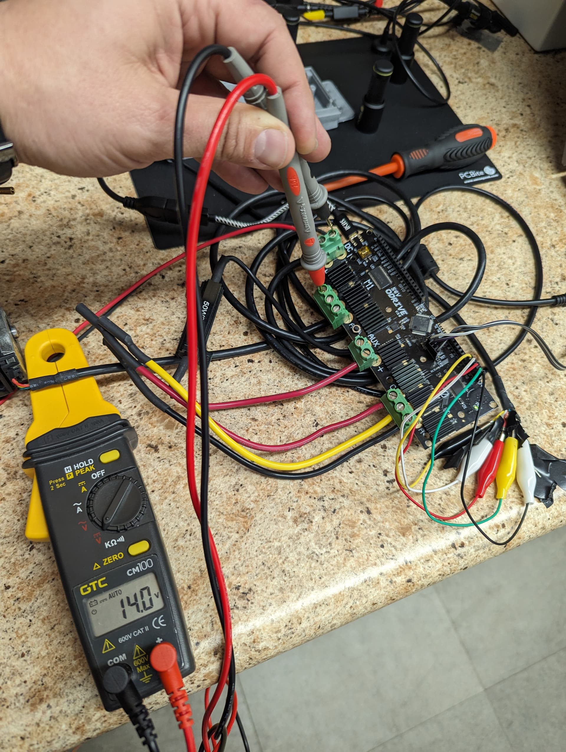
In open loop mode powered from a battery, current could rise very high depending on the motor’s resistance. Maybe a protection on the ODrive is activated? You can add a multimeter in series to the battery to monitor the current consumption…
msm,
As a troubleshooting step, are you able to test the driver alone?
This may be a bit rudimentary for what you are trying to do. I recently have been working with this board and was not getting expected results with a motor. This step gave me more confidence to proceed with tuning the motor.
/*
    Odrive robotics' hardware is one of the best  BLDC motor foc supporting hardware out there.

    This is an example code that can be directly uploaded to the Odrive using the SWD programmer.
    This code uses an encoder with 500 cpr and a BLDC motor with 7 pole pairs connected to the M0 interface of the Odrive.

    This is a short template code and the idea is that you are able to adapt to your needs not to be a complete solution. :D
*/
#include <SimpleFOC.h>

// Odrive M0 motor pinout
#define M0_INH_A PA8
#define M0_INH_B PA9
#define M0_INH_C PA10
#define M0_INL_A PB13
#define M0_INL_B PB14
#define M0_INL_C PB15
// M0 currnets
#define M0_IB PC0
#define M0_IC PC1
// Odrive M0 encoder pinout
#define M0_ENC_A PB4
#define M0_ENC_B PB5
#define M0_ENC_Z PC9


// Odrive M1 motor pinout
#define M1_INH_A PC6
#define M1_INH_B PC7
#define M1_INH_C PC8
#define M1_INL_A PA7
#define M1_INL_B PB0
#define M1_INL_C PB1
// M0 currnets
#define M1_IB PC2
#define M1_IC PC3
// Odrive M1 encoder pinout
#define M1_ENC_A PB6
#define M1_ENC_B PB7
#define M1_ENC_Z PC15

// M1 & M2 common enable pin
#define EN_GATE PB12

// SPI pinout
#define SPI3_SCL  PC10
#define SPI3_MISO PC11
#define SPI3_MOSO PC12

// Motor instance
//BLDCMotor motor = BLDCMotor(7, 0.039, 270);
BLDCDriver6PWM driver = BLDCDriver6PWM(M1_INH_A,M1_INL_A, M1_INH_B,M1_INL_B, M1_INH_C,M1_INL_C, EN_GATE);


void setup(){

  // pwm frequency to be used [Hz]
  driver.pwm_frequency = 25000;
  // power supply voltage [V]
  driver.voltage_power_supply = 20;
  // Max DC voltage allowed - default voltage_power_supply
  driver.voltage_limit = 20.0;
  // driver init
  driver.init();

   // enable driver
  driver.enable();

  _delay(1000);
}

void loop(){

driver.setPwm(12,13,14);

 delay(1);
}
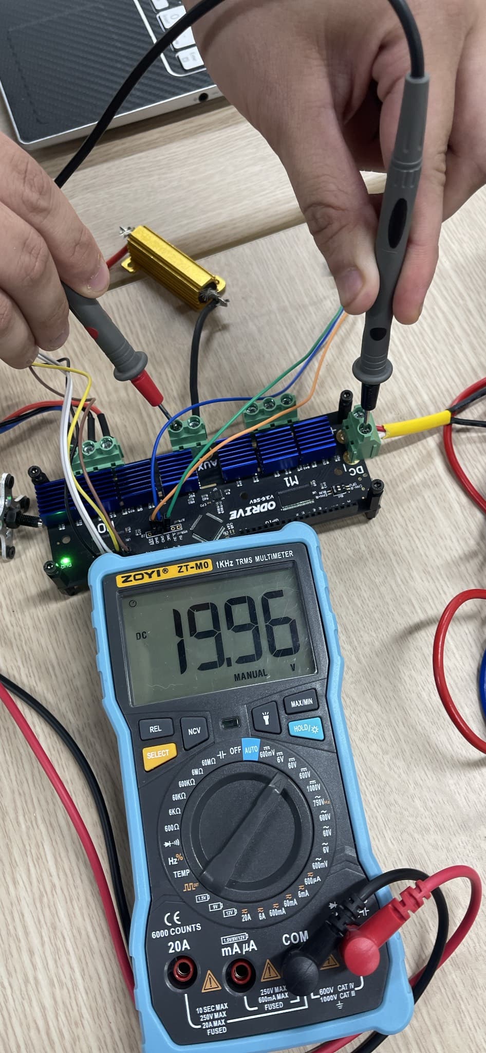
My setup was running off a Milwaukee battery at 19.5 volts. Phases disconnected from the motor.
Hi Kai, I’m a bit late here, but I used exactly your code to test my Odrive V3.6 but no luck. I hooked up the power to a 20V DC Source, uploaded the code through ST-Link. The uploading seemed successful but when I measured the phases with a multimeter it didn’t read the values that was set by the code.
Also as mentioned by msm in his other post, it seems that the USB on board only works when the board is loaded with its default firmware from Odrive. So at this time I don’t really have any way to verify if the hardware works with the custom code.
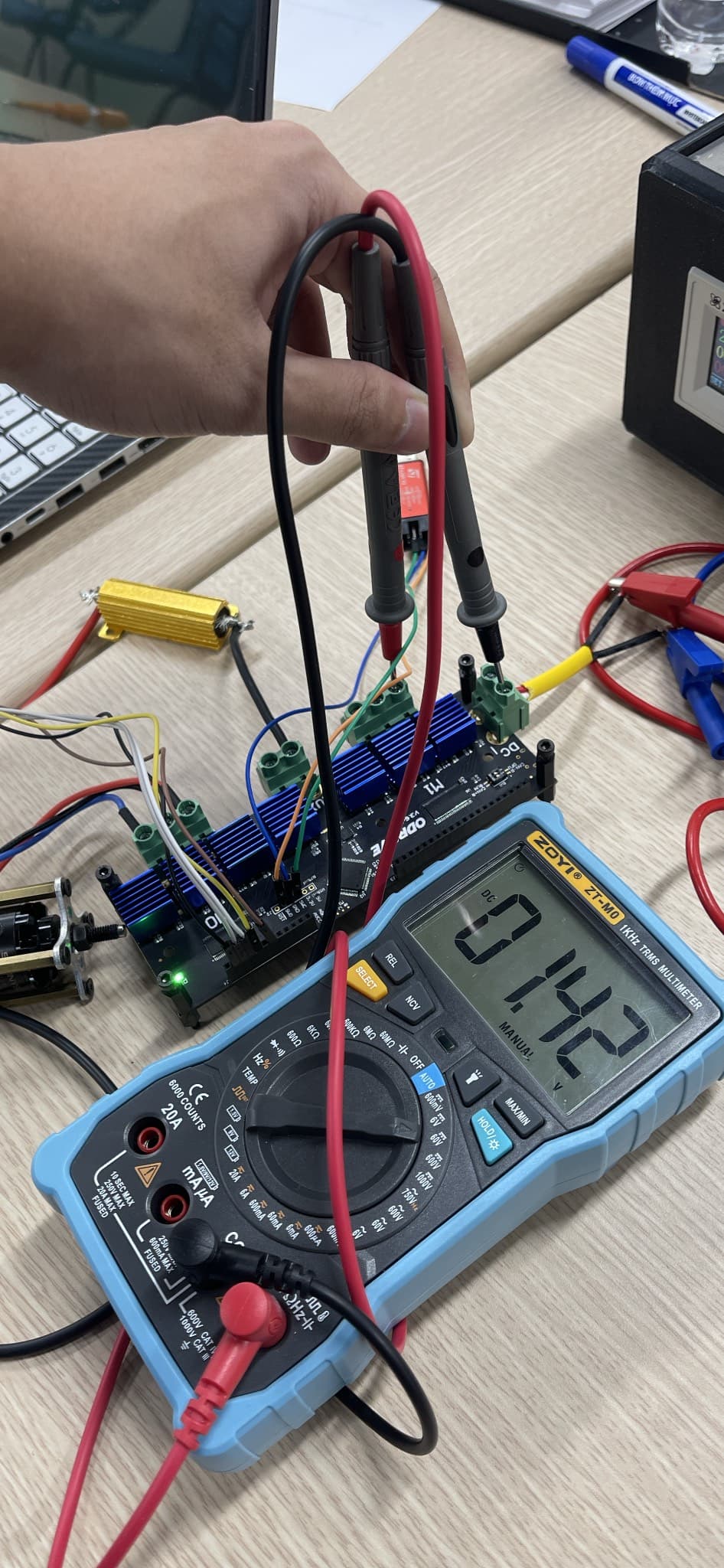
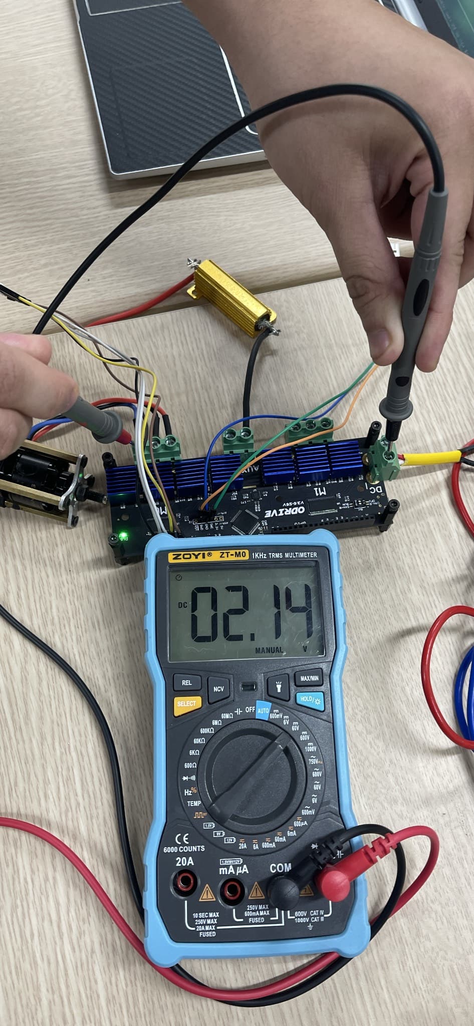
, I disconnected the brake resistor otherwise it would draw all the current and eat up all the volt.I uploaded your code that sets voltages to M1 by 12-13-14 but didn’t get the expected result:
I find it odd that you needed to remove the resistor.
On the M1 terminal, can you screw the terminal all the way down to verify that the actual screw is making contact with the bottom of the connector?
When you changed to M0 in the code, the photo shows that you left the motor connected, but you did receive a different voltage measurement… the power would have to go through the coils of the motor.
It would be difficult, but you could place a probe from an oscilloscope between the micro and the driver chip to verify output… I did some testing on this device to gain confidence prior to getting the Odrive working.
My board is from Makerbase, a 3rd party I believe. I actually found the problem, turns out I didn’t need to switch to DFU mode when uploading the code. I just let it stay at run mode and it is working fine now.
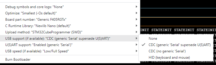
However I couldn’t get the micro-usb port of the board to be recognized by my computer. It could only be recognized as a COM port if I flashed the board with its default firmware. Are you using the onboard micro-usb for serial or are you using USB to UART to monitor?
Thank you Kai, I was away busy with some stuff and just got back to testing my Odrive today.
So it’s actually my first time working with an STM32 using arduinoIDE and it’s quite finicky at first. But I selected the USB option like yours, reuploaded the code and it’s working fine now. Really appreciate your time!