NUCLEO-64 G431RB: BLDC outputs not in phase?

Hi there, I recently switched to STM32-NUCLEO for work on FOC with BLDC. After I got things up and running, I noticed that Even at motor.voltage_limit=0 (0 commanded voltage to motor), I was drawing higher than expected current from the battery. I checked the U, V, W phases and found that the “W” phase has a shift from the other phases.
// PHASE U=GPIO9, V=GPIO5, W=GPIO6, En=GPIO8
BLDCDriver3PWM driver = BLDCDriver3PWM(9, 5, 6, 8);

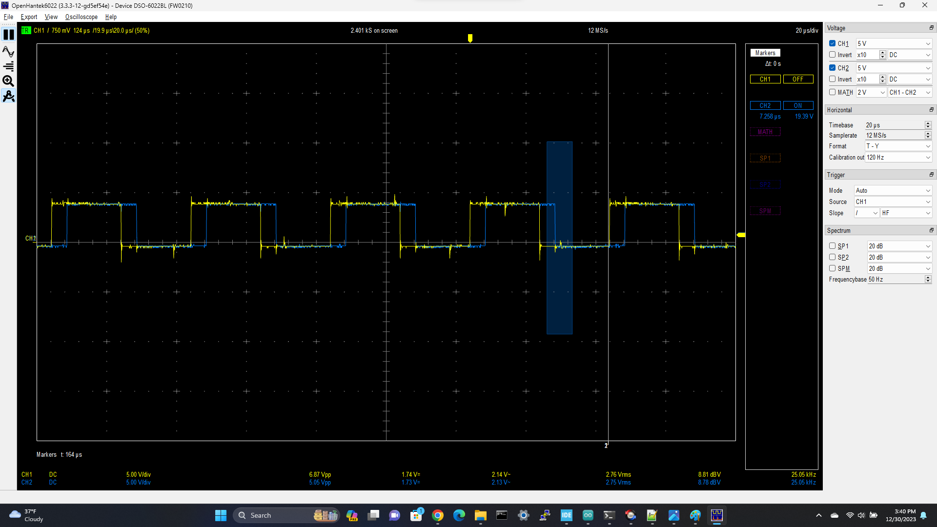
I checked the GPIO output driving the phase, and sure enough, while the U and V outputs are in perfect sync, the W phase (driving by GPIO#6) is shifted by quite a bit (see below). I tried switching from GPIO#6 to another GPIO, and the problems follows to whichever GPIO I choose.

Scope trace of GPIO phase outputs
driver.voltage_power_supply = 12;
driver.voltage_limit = 12;
motor.voltage_limit = 0
YELLOW=U and V phase drive (GPIO 5,9)
BLUE = W phase drive (GPIO 6)

#include <SimpleFOC.h>

//#define CURSENS

// encoder instance
MagneticSensorI2C sensor = MagneticSensorI2C(AS5600_I2C);
BLDCMotor motor = BLDCMotor(7, 1, 2500);
// PHASE U V W En
BLDCDriver3PWM driver = BLDCDriver3PWM(9, 5, 6, 8);

#ifdef CURSENS
// inline current sensor instance
InlineCurrentSense current_sense = InlineCurrentSense(0.01f, 50.0f, A0, A2, _NC);
#endif

// commander communication instance
Commander command = Commander(Serial);
// void doMotor(char* cmd) { command.motor(&motor, cmd); }
void doTarget(char* cmd) {command.scalar(&motor.target, cmd);}
void doLimit(char* cmd) {command.scalar(&motor.voltage_limit, cmd);}
void doMotor(char* cmd) { command.motor(&motor, cmd); }

void setup() {

sensor.init();
// link the motor to the sensor
motor.linkSensor(&sensor);

// driver config
// power supply voltage [V]
driver.voltage_power_supply = 12;
driver.voltage_limit = 12;
driver.init();
// link driver
motor.linkDriver(&driver);
// link current sense and the driver

#ifdef CURSENS
current_sense.linkDriver(&driver);
// current sense init and linking
current_sense.init();
motor.linkCurrentSense(&current_sense);
motor.torque_controller = TorqueControlType::foc_current;
// Q
motor.PID_current_q.P = 50;
motor.PID_current_q.I = 100;
motor.PID_current_q.D = 0;
motor.PID_current_q.limit = 10;
motor.PID_current_q.output_ramp = 500;
motor.LPF_current_q.Tf = 0.1;
// D
motor.PID_current_d.P = 0;
motor.PID_current_d.I = 0;
motor.PID_current_d.D = 0;
motor.PID_current_d.limit = 10;
motor.PID_current_d.output_ramp = 500;
motor.LPF_current_d.Tf = 0.1;
#endif

//motor.controller = MotionControlType::torque;
motor.controller = MotionControlType::velocity
// default voltage_power_supply
motor.voltage_sensor_align = 2;
motor.voltage_limit = 1;
motor.current_limit = 10;
motor.velocity_limit = 40;
// contoller configuration based on the controll type
motor.PID_velocity.P = 0.1;
motor.PID_velocity.I = 0.1;
motor.PID_velocity.D = 0;
motor.PID_velocity.output_ramp = 1000;
motor.PID_velocity.limit = 12;
// angle loop controller
motor.P_angle.P = 10;
motor.LPF_velocity.Tf = 0.01;

// set the inital target value
motor.target = 0;

Serial.begin(921600); // WARNING: low value like 115200 cause distorted FOC
motor.useMonitoring(Serial);
motor.monitor_variables = _MON_TARGET | _MON_VOLT_Q | _MON_VOLT_D | _MON_CURR_Q | _MON_CURR_D | _MON_VEL | _MON_ANGLE; // monitor target velocity and angle

//motor.foc_modulation = SpaceVectorPWM;
// initialise motor
motor.init();
// align encoder and start FOC
motor.initFOC();
// commnads
command.add(‘T’, doTarget, “target”); // ssss space
command.add(‘L’, doLimit, “voltage limit”);
command.add(‘M’,doMotor,“motor”);
_delay(1000);
}

void loop() {

// iterative setting FOC phase voltage
motor.loopFOC();
// iterative function setting the outter loop target
motor.move();
// motor monitoring
motor.monitor();
// user communication
command.run();

}

To put it more succinctly: In FOC mode when you command the motor voltage to zero, Phases U, V, W should just be the PWM carrier and should all be identical. In my case, U and V are identical, but W has a phase offset, which I tracked back to the phaseW GPIO

Can it be the pins are on different timers and the timers are not in sync?

That will be the issue. You should choose three pins from the same timer. You can add the build flag

-DSIMPLEFOC_STM32_DEBUG

to your build, and add a SimpleFOCDebug::enable(Serial); near the start of your setup… then the library will print the timer configuration it is using. I’ll be we’ll see that the phase W is on a different timer from the other two.

Timers can be configured in master/slave mode to be synchronized. I am not sure if it was explored in the past, and if it is of interest for SimpleFOC.

It would certainly be interesting to sync the timers, but in my limited research so far I only found the master/slave triggers as a way to do it. On other MCUs there are things like timer start registers which allow you to start arbitrary sets of timers together at the same time. I haven’t found such a mechanism for STM32.

But using triggers between timers will add yet more complexity to the already complex stm32 PWM driver :frowning:

The timers could be any timers - it’s not guaranteed that TIM1 is one of them. So it would need code that sets up triggers between arbitrary timers, but not all timers can trigger each other… I haven’t checked yet checked into if there are MCU specific differences between this as well, e.g. on some MCU series some timers can trigger each other, and on others not. If that were the case, it would add even more complexity, since there is also no information about this in the Arduino PinMaps…

So I’ve just left it as an idea for now - I think we’d have some other things to solve first which are perhaps higher priority.

I had a quick look, the information what timer can be a slave seems to be available here, but what ITRX triggers should be used for what master timer/slave timer seems to be complicated and only in the datasheet of each chip:

Not worth it.

You can add the build flag
-DSIMPLEFOC_STM32_DEBUG
on your build, and add a SimpleFOCDebug::enable(Serial); near the start of your setup

I think you mean SimpleFOCDebug::enable(&Serial); right?

Did this:
void setup() {
Serial.begin(921600);
SimpleFOCDebug::enable(&Serial);
delay(5000);

Did this:
{platform.txt} in folder: C:\Users\sgord\AppData\Local\Arduino15\packages\STMicroelectronics\hardware\stm32\2.7.1

compiler.extra_flags=-mcpu={build.mcu} {build.fpu} {build.float-abi} -DVECT_TAB_OFFSET={build.flash_offset} -DUSE_FULL_LL_DRIVER -mthumb “@{build.opt.path}” -DSIMPLEFOC_STM32_DEBUG

But I don’t see any new information from the serial port??? What am I doing wrong?

Where’s the best place to define SIMPLEFOC_STM32_DEBUG??? Everyplace I tried it somehow got undefined. I had #define it right in the source file stm32_mcu.cpp. Anyway, here’s what I got:

TIM3-CH2 TIM3-CH1 TIM2-CH3 score: 2
TIM3-CH2 TIM8-CH2N TIM2-CH3 score: -3
TIM3-CH2 TIM16-CH1 TIM2-CH3 score: 3
TIM8-CH2 TIM3-CH1 TIM2-CH3 score: 3
TIM8-CH2 TIM8-CH2N TIM2-CH3 score: -3
TIM8-CH2 TIM16-CH1 TIM2-CH3 score: 3
STM32-DRV: best: TIM3-CH2 TIM3-CH1 TIM2-CH3 score: 2
STM32-DRV: Configuring high timer 3
STM32-DRV: Configuring high channel 2
STM32-DRV: Configuring high timer 3
STM32-DRV: Configuring high channel 1
STM32-DRV: Configuring high timer 2
STM32-DRV: Configuring high channel 3
STM32-DRV: Restarting timer 3
STM32-DRV: Restarting timer 2

So yes, it seems that ch3 is using timer2, while CH1/CH2 are using TIM3.

After looking through the IO grid of my NUCLEO-G431RB board, unfortuantely it’s impossible to configure the jumpers on my FOC-SHIELD to get all 3 timer channels on one timer :(. Is anyone aware of a NUCLEO board which would work with the FOCshield?

In platformio add this will define it in all the files

build_flags = -DSIMPLEFOC_STM32_DEBUG

build_flags = -DSIMPLEFOC_STM32_DEBUG

Sorry for the stupid question… I’m fairly new to the arduino environment. Where exactly do I put that?

This is for platformio, not for the arduino IDE. Nevermind

Yeah, as expected, this is what is causing the misalignment.

in principle, the misaligned configuration will work, although as you observed it isn’t optimal.

Unfortunately the shield is of course designed to work with Arduino UNO boards, to match their PWM pins. So while the Nucleo boards generally work, unfortunately it can’t be guaranteed that all the pins come from one timer.

One simple solution would be to use jumper wires to connect the two boards, rather than plugging them directly - of course this is “messy”, but you can make any connections you want.

Another option could be to make a simple adapter PCB, which has the Arduino headers on top and the Nucleo 64 headers on the bottom, and makes the required connections the way you want.

Or to solve it in software, you could add the triggers specifically for your situation to the PWM initialisation code - but this code is unfortunately quite complicated.

That is for PlatformIO. For ArduinoIDE you have to add it in the platform or board files, the way you were doing. But adding it directly in the header is also fine.

Below is the debug output for all channels on TIM1. I was surprised to see a low score (1), or are they using “golf scoring” where lower is better?

TIM1-CH1 TIM1-CH2 TIM1-CH3 TIM1-CH4 score: 1
STM32-DRV: best: TIM1-CH1 TIM1-CH2 TIM1-CH3 TIM1-CH4 score: 1
STM32-DRV: Configuring high timer 1
STM32-DRV: Configuring high channel 1
STM32-DRV: Configuring high timer 1
STM32-DRV: Configuring high channel 2
STM32-DRV: Configuring high timer 1
STM32-DRV: Configuring high channel 3
STM32-DRV: Configuring high timer 1
STM32-DRV: Configuring high channel 4
MOT: Monitor enabled!
MOT: Init

Yeah, the score is like a cost function, so lower cost is better :slight_smile:

Thanks :slight_smile: anyway, this resolved this issue. Much appreciated!

Hi,
I have just received ny Nucleo-G43KB, but cannot find enough info to set up the right pins for PWM. @sgordon777 you said your issue was resolved, what pins did you end up using. I would like to try 3PWM or 6PWM if possible.

However I need to know the pin names i.e PA2, PA7 etc …

@Antun_Skuric wrote a tool for working out pins/timers for stm32. I think this is the one for the board you mentioned:

Brilliant, just the ticket … thanks