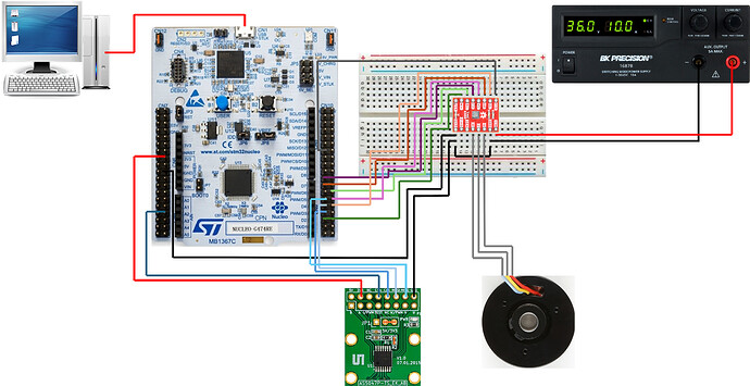
I’m using a ROB-20441 motor from sparkfun driven in 6PWM mode by a TMC 6300 running on a STM32G474RE, with an AS5047P magnetic sensor. I’m powering the AS5047P with 3v3 from the G474, and have the jumper and resistors configured for 3v3.
I have been running it in velocity open loop, and get motion. For my application, I need to be able to achieve a steady 15Hz rotational frequency (94.2 rad/s rotational velocity).
Regular monitoring of the angular position of the motor and verification of the rotational velocity is needed. Currently, the velocity output is rather noisy.
The velocity output can be cleaned up significantly by only updating the sensor and calling sensor.getVelocity() every 1000 loops, but it’s still not a useful value (eg when set to 94.2 rad/s, the velocity is reported as anywhere from 20-70 with occasional -200s).
I am using the built-in ring magnet on the ROB-20441 and it is approximately 1mm from the AS5047P, so there should be sufficient magnetic field strength for the sensor.
Here is an example of the readings from the sensor while the motor is stationary:
| position | velocity |
|---|---|
| 5.43 | 2.12 |
| 5.50 | 3.50 |
| 5.45 | -2.72 |
| 5.46 | 0.85 |
| 5.50 | 1.61 |
| 5.45 | -2.12 |
| 5.41 | -2.31 |
| 5.43 | 1.14 |
| 5.43 | 0.23 |
| 5.54 | 5.33 |
| 5.39 | -7.42 |
| 5.37 | -1.03 |
| 5.61 | 11.80 |
| 5.42 | -9.16 |
Here is the velocity open loop code I’ve been tinkering with:
#include <SimpleFOC.h>

BLDCMotor motor = BLDCMotor(4);
BLDCDriver6PWM driver = BLDCDriver6PWM(PA8, PB13, PA9, PB14, PA10, PB15);
MagneticSensorSPI sensor = MagneticSensorSPI(PA4, 14, 0x3FFF);

SPIClass SPI_1(PB5, PB4, PB3);

int i_max = 5000;
int i = 0;
int a_max = 50;
int a = 0;
int l = 0;

float target_velocity = 50;

void setup() {

  // driver config
  driver.voltage_power_supply = 9;
  driver.voltage_limit = 7.4;
  driver.pwm_frequency = 20000;
  // dead_zone [0,1] =  default 0.02 - 2%
  driver.dead_zone = 0.02;
  driver.init();
  // link the motor and the driver
  motor.linkDriver(&driver);

  // Magnetic Sensor
  sensor.init(&SPI_1);

  motor.linkSensor(&sensor);

  motor.voltage_limit = 7.4;

  motor.foc_modulation = FOCModulationType::SinePWM;

  // open loop control config
  motor.controller = MotionControlType::velocity_openloop;

  // init motor hardware
  motor.init();

  Serial.begin(115200);
  Serial.println("Motor ready!");
  Serial.println("Target velocity set to: ");
  Serial.print(target_velocity);

  _delay(2500);
}

void loop() {
  //sensor polling downsample
  if (l % 1000 == 0) {
    sensor.update();
    Serial.print(sensor.getMechanicalAngle());
    Serial.print("\t");
    Serial.print(sensor.getVelocity());
    Serial.print("\n");
  }
  l++;

  //slow ramp in velocity
  if (i % (i_max / a_max) == 0 && a < a_max) {
    a++;
  }
  i++;

  motor.move(a*(target_velocity / a_max));
}
What additional filtering or changes would you suggest I make to help my configuration run better?
I imagine that velocity closed loop operation would be produce a more steady output, but I haven’t been able to get even the torque control closed loop example to work.
One issue that might be contributing to torque control not working is that I am unsure of the number of pole pairs in this motor. The datasheet from Sparkfun is rather sparse but does indicate that there are 8 poles (so 4 pole pairs), but from what I’ve gathered this would an unusual configuration.
I have tested open loop function and the utility sketches with various pole pair values set (4-11), and haven’t noticed improved performance with any one particular setting.
The sensor, while a bit noisy when updated frequently, appears to be tracking position fine and reports an increase in angle of 2Pi when I turn the motor by hand by a full revolution.
However, when I run the ‘find_pole_pairs_number.ino’ example sketch, it turns by about 120 degrees in one direction, then about 30 degrees in either direction, then snaps to a nearby position and starts vibrating.
The number of pole pairs estimated by the sketch varies widely from 4 to 11.
Similarly, the ‘find_sensor_offset_and_direction.ino’ example sketch calculates a different sensor offset each time I run it.
When running the ‘find_kv_rating.ino’ example, it fails pole pair check and then starts oscillating about a fixed position, giving wildly varying kv values.
I’ve also done some reading on the current sensing implementation in SimpleFOC, and while I should be able to implement it in this setup (TMC 6300 breakout board I am using has a current sensing pin), I don’t quite understand how to wire it based on the descriptions in the wiki.
In the examples on the wiki it appears the analog pins are being used, but what are they connected to?
Additionally, I am not sure what the winding configuration of the motor is (wye vs delta) and so cannot determine the phase resistance.
Sorry for so many questions, I’m feeling a bit out of my depth. If you could use any additional information, please don’t hesitate to ask. I’ll take all the help I can get, in any of these areas!
