First of all, appreciate your lib of foc on arduino, I have been searched for this for a long time. I was using drv8313 and arduino uno to drive a 28mm brushless motor with 12N14P at 8V. Open loop example was applied and i found that when the motor keeps static, it make very loud noise and give off heat(not very hot). By the way, in this case i didn’t use any position sensor and the resistance is about 4 ohm. Why would this happen? Is there a way to make it quiet when it keeps static? Thanks a lot!
one more thing to mention, when i add TCCR3B = (TCCR3B & 0xF8)|0x01 in the example code, which gives a higher frequency of pwm, the frequency of noise rises as well.
Here you will see that the current I the motor feels is going to depend on the voltage V you set (motor.voltage_limit) and the velocity w the motor turns with:
I = ( V - Ke*w ) / R
So the smaller the velocity the higher the current. It is a bit contra intuitive I know but this comes from the fact that the motor generates voltage when it is turning and if you keep the voltage V fixed, for higher velocities you will effectively put:
V_motor_feels = V - V_generated = V - Ke*w
Ke is electrical constant of the motor.
So what I want to say is since your motor has resistane R=4 Ohm, for V=8 Volts you will have current of:
I = (8 - Ke*0)/4 = 2 Amps
That is a lot for the motor of 28mm. This kind of current can create the noise as well.
So what you can do it to reduce the motor.voltage_limit together with target_velocity.
Basically when you have target velocity small reduce the motor.voltage_limit to a small value or even 0.
Regarding this:
I would not do this because the pwm timers have been configured to inside the library to produce centered pwm at maximal frequency possible. You can double the frequency of the pwm inside Arduino with one of these commands, but it will not be centered any more and you risk to burn the motor and have much worse performance.
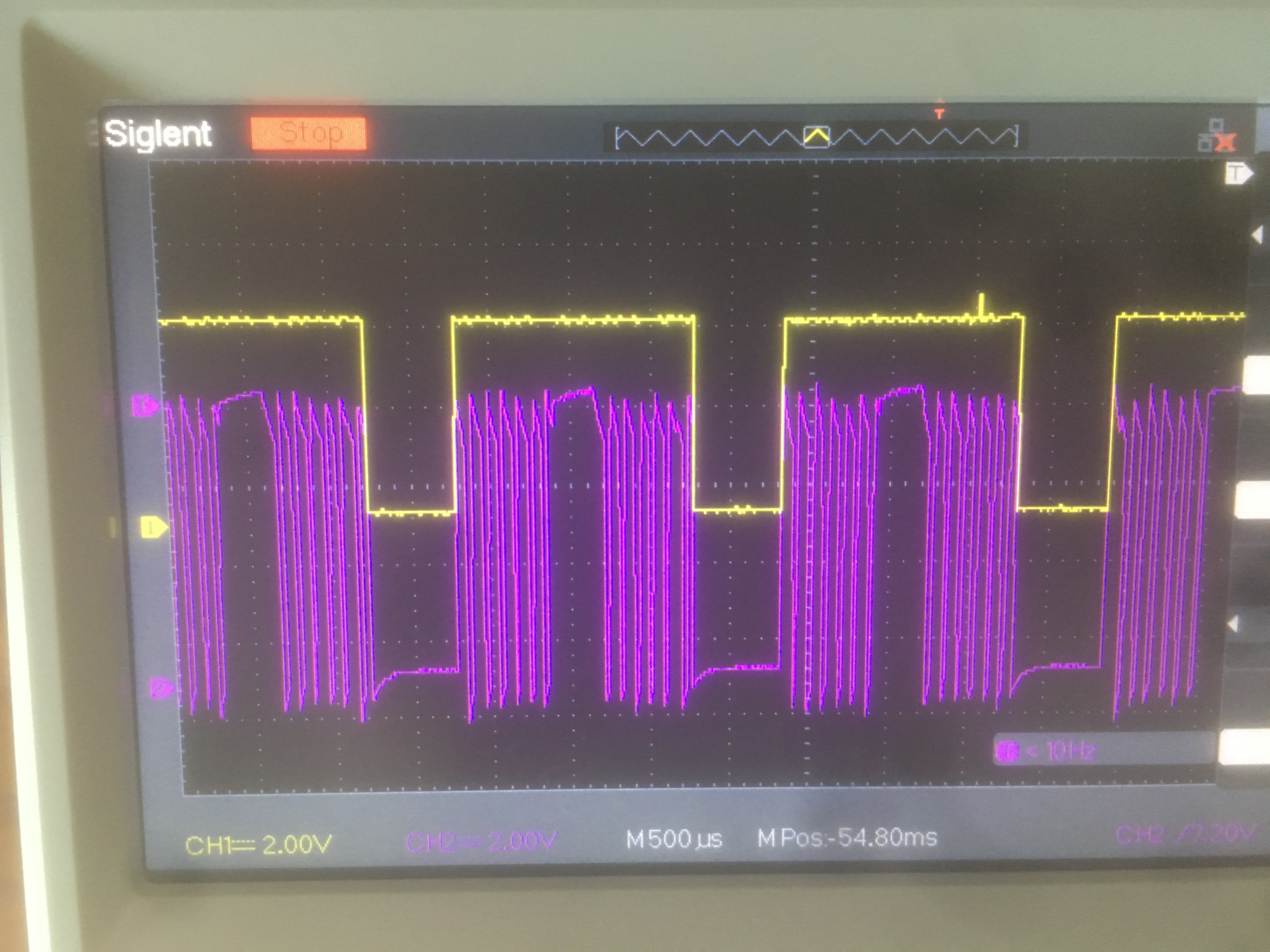
To close loop,I purchashed a megnetic sensor as5600. The sensor works well with I2C. However, when I tried the close loop control code, the motor just shaked. Then i decided to check the waveform with oscilloscope. One pwm channel and its’ corresponding motor output is shown as below.
yellow line is the pwm and pink line is output. As I anticipated, they should keep the same waveform(Is this right?), meanwhile they did not. So I suspect there are something wrong with my motor driver DRV8313. What’s your opinion on this phenomenon? Thanks a lot!
This behavior is definitely not good. I am not sure what could be the reason for it.
Could you just quickly list the motor, microcontroller and driver you are using.
Does the open-loop work well or you have the same behavior for it?
Do you ever lose the I2C communication or is it present the whole time? (even during the behavior from picture)
Can it be that your current limit is causing this waveform?
What is the motor winding resistance? The drv8313 is a great driver for gimbal type motors but not so much for normal RC low resistance. I make some really small driver boards for the drv8313 so would be interested to know how yours are set up.
After some trials, I figured out that the reason shall be incorrect pid parameter. Default pid is not suit for my motor and now i can make it run at stable state. Thank you so much!
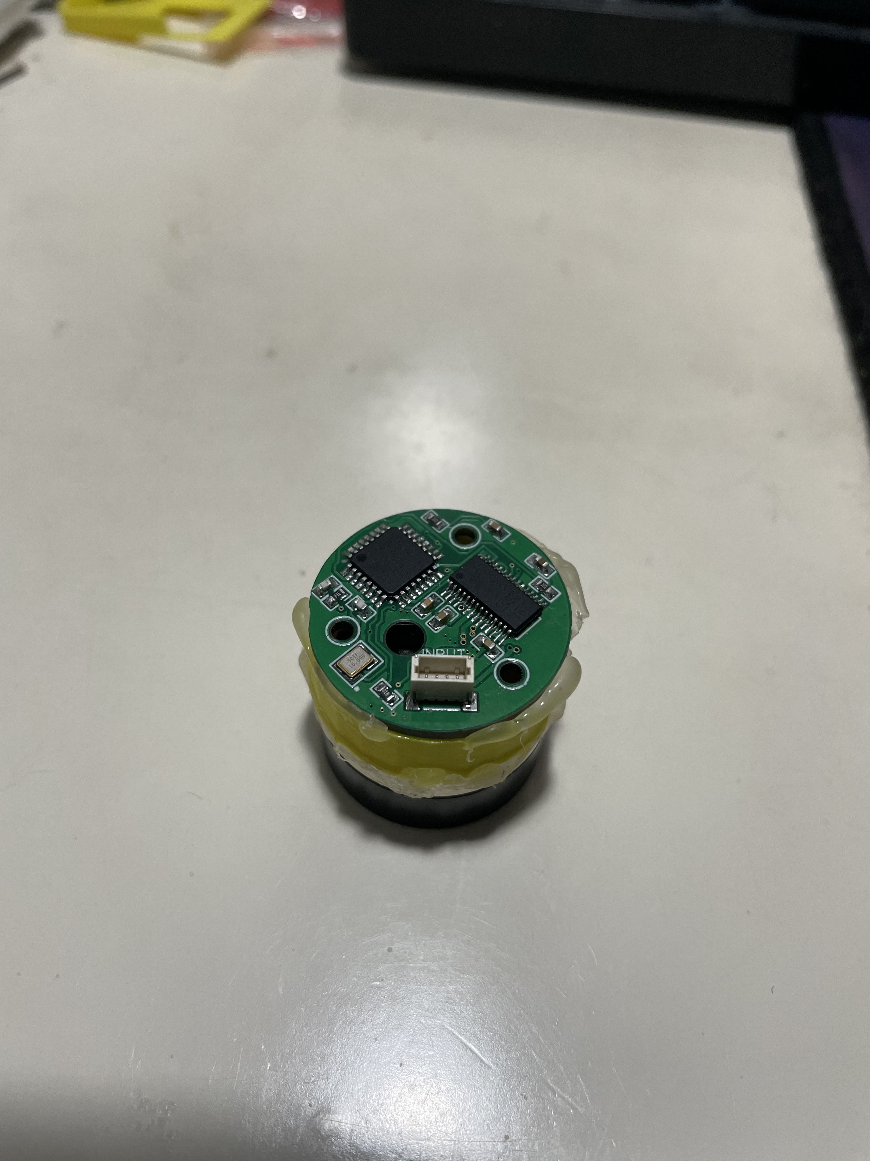
My BLDC is 2804 gimbal motor, resistance is 6ohm. I designed my own pcb, which can be attached on the motor. Hardwares are atmega328p, drv8313, as5600. The semi-finished product looks like this
Do you have a pdf of schematic? I always like to look at how people have designed their custom boards! No worries if you want to keep hold of your secret sauce
I will open source all the files and demonstrate what I have accomplished after it’s really finished. However, i’m not sure how many days would it cost
Another problem! To be brief, is there a way to set the initial angle of magnetic sensor(such as as5600)? I mean if the motor didn’t rotate between two power up, I found that the two initial angles sometimes are the same but sometimes are totally different, which troubles me in this project.
The AS5600 cannot be programmed with a zero position, but the AS5048B, and some of the other AS sensors can.
In reality, it should not matter because the SimpleFOC init routines will detect the electric rotation zero position, and map the sensor’s current values to make everything work.
This should be fine if you run the init and initFOC routines each time you start up. If you’re trying to store the initialisation values, then this would be a problem of course… in this case maybe try a AS5048B instead? Its also more accurate (although also more expensive).