Good Afternoon,
I’m looking for some help in getting the torque control mode to work for a BLDC motor.
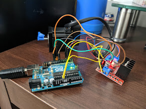
Hardware:
- Arduino UNO R3
- L298N (I know this is not ideal for BLDC motors, but it’s what I have right now)
- 3pp bldc motor with hall sensors motor datasheet
Circuit: right now I am powering everything off of the arduino 5V, I plan on getting a 12V power supply soon. Software interrupts are used for the hall sensors.
I am following the tutorial linked here: https://www.youtube.com/watch?v=ENGGh0ajE2M
I’ve been able to:
- Use open loop velocity to spin the motor up to 15 rad/s
- Read that the sensor measures 6.28 for a rotation of the motor
I’ve been trying to:
- Use the torque controller (motor doesn’t spin at all)
- Use the closed loop velocity controller (motor vibrates)
When the initFOC runs, the motor spins back and forth a few degrees, stops, and I get the following message:
MOT: Init
MOT: Monitor enabled!
MOT: Init
MOT: Enable driver.
MOT: Align sensor.
MOT: sensor_direction==CW
MOT: PP check: fail - estimated pp: 4.50
MOT: Zero elec. angle: 1.05
MOT: No current sense.
MOT: Ready.
Setup complete
Any help is greatly appreciated.
Code is largely copy+paste but is shown below:
#include <SimpleFOC.h>
#include <PciManager.h>
#include <PciListenerImp.h>

HallSensor sensor = HallSensor(2, 3, 4, 3); // hA, hB, hC, pole pairs

BLDCMotor motor = BLDCMotor(3);
BLDCDriver3PWM driver = BLDCDriver3PWM(11, 10, 9);

void doA(){sensor.handleA();}
void doB(){sensor.handleB();}
void doC(){sensor.handleC();}

PciListenerImp listenA(sensor.pinA, doA);
PciListenerImp listenB(sensor.pinB, doB);
PciListenerImp listenC(sensor.pinC, doC);

float target = 0.5;

void serialLoop() {
  static String received_chars;
  while (Serial.available()) {
    char inChar = (char) Serial.read();
    received_chars += inChar;
    if (inChar == '\n') {
      target = received_chars.toFloat();
      Serial.print("Target = "); Serial.println(target);
      received_chars = "";
    }
  }
}

void setup() {
  Serial.begin(115200);

  // Sensor setup
  sensor.pullup = Pullup::USE_INTERN;
  sensor.velocity_max = 500;
  sensor.init();
  PciManager.registerListener(&listenA);
  PciManager.registerListener(&listenB);
  PciManager.registerListener(&listenC);

  // deactivate the OUT4 output
  pinMode(8,OUTPUT);
  digitalWrite(8,LOW);

  // Motor Setup
  driver.voltage_power_supply = 5;
  driver.voltage_limit = 5;
  driver.init();
  // link the motor and the driver
  motor.linkDriver(&driver);
  motor.voltage_limit = 5;   // [V]
  motor.velocity_limit = 18; // [rad/s]
  //motor.voltage_sensor_align = 1;
  motor.linkSensor(&sensor);
  //motor.PID_velocity.P = 1.0;
  //motor.PID_velocity.I = 0.0;
  //motor.LPF_velocity.Tf = 0.01;
  //motor.controller = MotionControlType::velocity;
  motor.torque_controller = TorqueControlType::voltage;
  motor.controller = MotionControlType::torque;
  //motor.controller = MotionControlType::velocity_openloop;
  motor.useMonitoring(Serial);
  motor.init();
  motor.initFOC();

  Serial.println("Setup complete");
  delay(1000);
}

void loop() {
  serialLoop();

  //motor.PID_velocity.P = target;
  motor.loopFOC();
  motor.move(target);

  //sensor.update();
  //Serial.print(sensor.getAngle());
  //Serial.print("\t");
  //Serial.println(sensor.getVelocity());

  motor.monitor();
}