Motor Shaft Velocity Spikes

I am unable to achieve constant velocity for my application. Here is a chart made in LabView that best describes the problem.

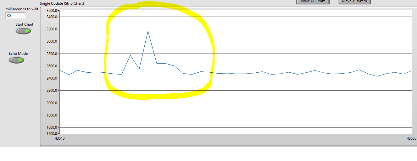
The LabView application plots the value of
motor.shaft_velocity
converted to microns per second every 30ms. We do this by having 2pi radians be equal to the pitch of the permanent magnets on the stage and pole pairs defined as 1.

The motor’s position is stable when not moving. The encoder loop runs ~40,000 times per second with an accuracy and precision of ~100nm.
The motors and encoder are within the stage at this link:

The maximum velocity is set to 2500um/s. An acceptable range would be 2400-2600um/s for my application, so those spikes must go as they are out significantly out of the range. There are also spikes in the negative direction.

When this image was taken, the PID_velocity values were all default, but I had tried tuning these with various methods achieving similar/worse results. Changing the D to any non-zero value made the motor produce a loud noise, which makes it difficult to tune since the noise would also be unacceptable for the application. I also tried changing the downsampling and LPF values, both of which still showed spikes in the velocity graph.

The driver being used is the MP6540 using high side and low side drivers, instantiating the motor with
BLDCDriver6PWM driver = BLDCDriver6PWM(PHASE_A ,PHASE_B ,PHASE_C);
BLDCMotor motor = BLDCMotor(POLE_PAIR, 9, 80, .0015);
motor.controller = MotionControlType::angle;
Drive voltage has been varied between 12V-30V with no effect.

Any help or ideas are appreciated.

This might sound counter intuitive but setting an encoder loop too fast is not good. It means that the deltas betweeb samples is more noisy which can effect tuning - particularly that D term. Try sampling at 2000 times per second and retrying introducing some D. Do you have any I term, could that spike be integral windup?

Might be worth showing your full code.

Thanks for your response. I tried your suggestion just now by setting the downsample to 20 to bring the sample rate to ~2000 and introduced a D. With the velocity P I and D values being 5, 10, and 0.001 respectively, the spikes were slightly reduced, as can be seen here:

One of the issues I have is the motor starts to groan a little when the D is introduced… is there a solution for that? Also the spikes are unfortunately still too drastic to be acceptable.

I will work on cleaning up the code and posting it tomorrow.

2500u/s = how many encoder pulses?

Trying to get a feel for how much precision you have with that sensor at that speed.

If you strip out the P=4, I=0 and D=0 does it look smoother? What speed is it? I kinda want you to find a value for P on its own where it’s doing about 1800u/s. Then maybe add a little I.

And experimenting with the lpf might help
’motor.LPF_velocity.Tf = 0.01;’
May help

2500u/s = how many encoder pulses?

It is difficult to say since the encoder is not digital. The encoder I am using is part of Renishaw’s TONiC series, and the way we are getting positional data of the motor from it is by reading a pair of differential sinusoids in quadrature (90 degrees phase shifted).


The encoder must keep track of every quarter sine, at a minimum. Every 5um increment, at least, must be captured. This is the reason for not only running the encoder loop at such high speeds, but why it runs on a dedicated core.

If you strip out the P=4, I=0 and D=0 does it look smoother? What speed is it?

With the velocity P=4, I=0, D=0, LPF_velocity.tf =0.01, downsample=15, it does not look smoother, with the speed averaging ~2400 (before going out of control) when set to 2500.

I kinda want you to find a value for P on its own where it’s doing about 1800u/s. Then maybe add a little I.

At velocity P=0.75,I=0,D=0, the velocity jumps to ~2800 then eventually settles around 1800. It certainly looked smoother in the sense that if there were spikes they were a lot less of a change. Unsure of what you meant by a little I, I tried a few different values but here is a chart with I=1, which seemed to reintroduce the spikes:

Overall, the spikes were more rare, but still a problem. Here is the cleaned up code, for intellectual property reasons, this is a stripped down version of what is being run. Hopefully something will stick out to you that I missed.

#define PHASE_A 14,22
#define PHASE_B 13,23
#define PHASE_C 12,24

#define PICO_RAND_ENTROPY_SRC_ROSC 1
//True number is .000279 (encoder is in units of 100nm)
#define POLE_PAIR 1
#define MICRONS_TO_RAD (0.000027925268/POLE_PAIR)
#define RAD_TO_MICRONS (3580.986224*POLE_PAIR)


//--CORE 1--
void setup1(){
}

void loop1(){
 //this is where we interpret the sinusoids in quadrature to produce the variable nanometersMoved, which is in units of 100nm, calculated by
  calculateDistance();
}

float readSensor(){
  float radians = (( (double)1.0 * (double)nanometersMoved) * ( (double)MICRONS_TO_RAD));
  return radians;
}

void initSensor(){
}

GenericSensor sensor = GenericSensor(readSensor, initSensor);
BLDCDriver6PWM driver = BLDCDriver6PWM(PHASE_A ,PHASE_B ,PHASE_C);
BLDCMotor motor = BLDCMotor(POLE_PAIR, 9, 80, .0015);


//--CORE 0--
void setup() {
  
  //This does all of the gpio initiations
  stageSetup();
  
  sensor.init();

  driver.pwm_frequency = 20000;
  driver.voltage_power_supply = 24;
  driver.voltage_limit = 24;
  driver.init();
  motor.voltage_limit = 24;
  motor.linkDriver(&driver);
  motor.linkSensor(&sensor);
  motor.controller = MotionControlType::angle;
  motor.LPF_velocity.Tf = 0.01;
  
  motor.P_angle.output_ramp = 50/POLE_PAIR; //rad/s^2


  motor.PID_velocity.P = 0.75;
  motor.PID_velocity.I = 1;
  motor.PID_velocity.D = 0;

  motor.velocity_limit = 0.698132; //rad/s
  motor.foc_modulation = FOCModulationType::SinePWM; 
  
  motor.P_angle.P = 20;
  motor.P_angle.I = 0;
  motor.P_angle.D = .4;
}

void loop() {
	//target_angle is given via serial commands
	motor.move(target_angle);
	motor.loopFOC();
}

I have lots of questions!

You’ve set the velocity limit to be 2500um/s (0.698132 rad/s * 3580.98) but you also want a speed of 2500um/s. My head hurts as to how the control logic will deal with this. I’d set the velocity limit to be higher than target speed e.g. 2550 or 2600um, this will allow it to ‘catch up’ normally.

Have you tried to see if you can get a constant velocity using motor.controller = MotionControlType::velocity;. I suspect simplefoc will find things it much easier to get smooth velocity this way, but I guess you’ll ‘run out of track’ pretty quickly, but you might learn something. It is good to get the PID_velocity tuned before moving to position.

I’m a little suspicious of your Serial interface causing problems. It’s not great having serial running on same thread as simplefoc. Can you mock out the serial e.g. somehow get a basic planner running on simplefoc instead of receiving target angles over serial. At the very least I’d expect you to be running serial at high speeds e.g. 230400 or higher.

Is your off board planner (that is sending the serial angles) fully aware of the motor position? Or is it open loop? Both have problems, if it is aware of motor position (closed loop) then I imagine there is quite a lag going on - i.e. it is giving commands based on information that could be a few ms old. If it is unaware of motor position (open loop) then you may asking for angle steps that are unreasonably large.

Now that we know that you have a velocity and angle pid loop, I suspect others will be able to help you tune. But I think you’d normal tune the velocity PID in motor.controller = MotionControlType::velocity - get those sorted and then switch to angle to tune the other PID. It is too hard to tune both at the same time.

1 Like

Not sure if it makes any difference, but I’d define Pole_Pair as a double or float or leave it out completely, since it is 1 (in the example code anyways)

Hello everyone, thanks again for your help through all of this.

I had tried this before, but revisited it again after your suggestion. When graphing it out, it seems to not have made a difference whether I would be using motor.controller = MotionControlType::angle with the maximum velocity set to 2500um/s, or the maximum velocity being set higher (2600 um/s) and running the motor in motor.controller = MotionControlType::velocity with the target being 2500 um/s.

There shouldn’t be any issues related to the serial interface. The architecture is set up so that core 1 of the RP2040 microcontroller is solely responsible for reading the position of the motor by doing the calculations on the encoder data. This provides the nanometersMoved variable in the function readSensor() which acts as a GenericSensor for the SimpleFOC library. The serial interface is essentially us manually giving an angle for the motor to move to, which we keep within bounds of the stage.

Thanks for joining in, I will try changing that to see if it makes a difference and get back to you.

A quick update, for anyone curious:

Research papers on linear motors suggested using space vector modulation. Nearly half of the spikes were eliminated by simply changing
motor.foc_modulation = FOCModulationType::SinePWM;
to
motor.foc_modulation = FOCModulationType::SpaceVectorPWM;

While this was a great first step, it wasn’t enough, so we dug deeper.

It then took a couple of weeks before we realized that the source of the velocity spikes were due to an issue with how we were calculating the motor’s position in the function calculateDistance(). There were sudden changes in the motor’s position when the actual position had not changed, thus causing the PIDs to react drastically to compensate for it.

Thank you all for your help, the issue is resolved now and the system works as intended.

2 Likes

Thanks for posting back.

This is a really interesting use case (quite different to what most of us are doing) and its good to here a success story!