yep I linked it and it seemed to apply correctly as I could see the smoothing take effect in the first image of the previous reply. I’m at a loss with this motor ![]()
Have you tried tuning the PID parameters?
Valentine
Yep and sadly it doesnt seem to make much of a difference. What method do you use to tune your PIDs?
I use a hardware board with manual tuners, but that’s probably a little outside your envelope.
Valentine
Well folks I think I’ve found the issue… the hall sensors in this motor are absolutely cr*p.
After ruling out current sensing, and knowing that my driver setup was fine, I set the motor to open loop velocity and plotted the hall signals.
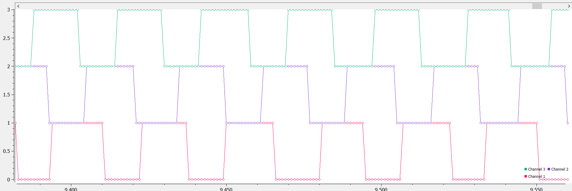
Look how terrible that is!!! At one point a state change on the blue hall happens at the exact time as the red hall signal…
For reference, here is a plot of a working motor:

I dont suppose anyone else has experienced this behaviour? and has anyone got any solutions?
Sadly I cant use any other form of sensors in this setup, so it may be time to investigate sensorless commutation
You said it works well with VESC ? Was it with he hall sensors or sensorless ?
A shift in the signals could be explained by hall sensor placement.
VESC also creates a hall table with angles measured during the calibration.
But it also looks like the ON states are not of equal width for the same hall sensor, so maybe problems with the magnets ?
If you don’t care about control at low/zero speed, you can try this flux observer sensor (with a PSU). Here is also an example. You will need to measure the motor parameters.
If the magnets are the problem I guess it could also impact the flux observer.
1 Like
I only tried sensorless when using the VESC which likely explains why it performed decently. My next experiment will be to hook up the halls to the VESC and see what issues it causes.
Yeah the patterns look really strange, not only is the phase shifted, but the widths in the on and off states fluctate quite a lot. Im going to contact the supplier and see if i can understand what exactly is the issue here
Awesome thanks for that sensorless code! Ill absolutely give it a go.
When you say try it with a PSU, is that just for safety incase it is unstable? In the end i intend on powering this motor from a VW golf GTE battery module which can certainly pack a punch if things go wrong
Because things can go bad if the motor parameters are wrong.
But I think you are using an overcurrent trigger as break input so it should be ok
Sweet yeah im using the timer break and it seems to do a pretty good job. I accidently shorted the phase leads and it cut off immediately
Ill give that sensorless example a go during the next week and i’ll let you know how I get on

Hot damn.
This looks like the halls are rattling inside. Some algorithms use only one hall so may be that’s why some algos work.
Try open velocity loop, that should be really quiet, then it’s definitely the hall sensors are loose inside.
Can you open the motor and pull the rotor out?
Valentine
Its so bizarre! I’ve never seen anything like it.
I think you’re correct about the hall sensors rattling, that would absolutely explain the inconsistency between the timings of the hall state changes. I’m going to see if I can get this thing open without breaking it… although it’ll be scary as it did cost quite a bit of money
I’ve ran some open loop velocity tests and it is essentially silent, so I think everything is pointing towards dodgy halls
1 Like
Hey @Candas1
I tried out the MXLEMMING flux observer and wow it works fantastically. Luckily I had the motor parameters from my experimentation with VESC and it fired up straight away, I’m pretty mind blown that sensorless FOC was this easy to add.
I added a start up boost where it applies higher currents below a certain RPM so it can get started reliably and it works every time.
I’m going to definitely try this on my 15kW mobility scooter’s sensorless motor in the near future
EDIT: It’s got me thinking how incredibly useful motor parameter extraction would be. If SimpleFOC had the ability to profile the motor then we would essentially have a library that is as capable as VESC, but is much more modular and flexible
2 Likes
Thanks a lot for the feedback.
I wanted to get feedback before publishing this in the dev branch and then in main branch of simplefoc.
Please let me know if anything is unclear about the docs or the code to use the “sensor”.
There are people on the discord discussing HFI, some of this code could be used to characterize motor parameters like inductance. It will take some time but it will be a good addition to the library.
So sensorless runs better on this motor than with the weird hall sensors ?
2 Likes
The example code was all I needed to get it working in under 15 minutes. I think its absolutely ready to be added to the dev branch, and probably even main tbh. Some supplementary docs online could maybe be good to express the need for good motor parameters, but in its current state it was essentially plug and play.
Ive tried it on my 15 pp hoverboard motor, 10pp inrunner motor, and will be trying it soon on a 3pp inrunner soon.
The difference between the flux observer and the dodgy hall sensors was night and day. With halls it barely ran, drew loads of current and sounded horrific. As soon as i fired it up with the FO it span up great, was very smooth and sounded identical to using the vesc
3 Likes
Hello again @Candas1,
I’ve been doing more testing and have found a bug in the mxlemming sensor (and maybe many more sensors?) which causes it to go crazy after running for a while. Consistently at ~35:30 minutes since boot, the motor makes a sudden very loud noise before my overcurrent protection kicks in, this happens repeatedly until power off, despite my target current being 0.
I was thinking that 35:30 mins is suspiciously half of 71 mins, which is the time to overflow for a 32 bit unsigned integer when incrementing in the microseconds. That’s when I noticed that angle_prev_ts is a signed long datatype and stores the timestamp in microseconds, which therefore will overflow at exactly 35:30 mins. I inspected these variables using a debugger and indeed the angle_prev_ts & vel_angle_prev_ts get clamped to 2,147,483,647.
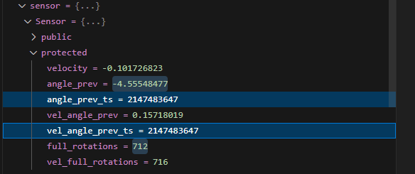
So essentially these timestamps become stuck at their maximum value after ~35mins, and this causes havoc for the FOC.
However, this is rather interesting because these variables are defined in the sensor base class, so surely this would also be an issue for many other sensor types as well?
2 Likes
Found the bug. Arduino-FOC-drivers/src/encoders/MXLEMMING_observer/MXLEMMINGObserverSensor.cpp at flux_observer · Candas1/Arduino-FOC-drivers · GitHub line 49, float now = _micros(); should be int32_t, not float. Those timestamp values are always used for deltas so wraparound will cancel out, but it only works with integer subtraction.
3 Likes
Thanks for sharing this. Need to check if I handle it in the right way.
2 Likes
Ah thanks. I will fix it.
2 Likes
I thought I need to find 36 minutes this evening to fix and test ![]()
So it’s just int32_t now = _micros();
1 Like