With the B-G431B-ESC1 driver, If I increase baudrate above 500000 bps, the ADC readings report close to 0 values. The serial output works, but the motor initialization fails:(I’ve added current logging during current sense alignment routine)
At 1M: (fail most of the time) 11:31:48.069 → MOT: Init 11:31:48.582 → MOT: Enable driver. 11:31:49.066 → MOT: Align sensor. 11:31:51.288 → MOT: sensor_direction==CCW 11:31:51.288 → MOT: PP check: OK! 11:31:51.994 → MOT: Zero elec. angle: 0.00 11:31:52.186 → MOT: Align current sense. 11:31:53.282 → Ia: -0.01 11:31:53.282 → Ib: -0.03 11:31:53.282 → Ic: -0.05 11:31:53.282 → CS: Err too low current, rise voltage! 11:31:53.282 → MOT: Align error! 11:31:53.282 → MOT: Init FOC failed. 11:31:53.282 → Motor ready.
I was suspecting a timing issue that, if the code is run too quickly, would prevent ADC to properly initialize, or something else, so I try to disable SimpleFOCDebug::enable(&Serial); and sure enough, the motor never get initialized.
I’ll try to add delays in the FOC internal initialization function to narrow this down, but I was curious to know if someone have an idea about this.
Also note that at the moment I’m using interupt based ABI encoder driver.
Here is my code
void setup() {
// use monitoring with serial
Serial.begin(115200);
// enable more verbose output for debugging
// comment out if not needed
SimpleFOCDebug::enable(&Serial);
encoder.init();
encoder.enableInterrupts(doA, doB);
motor.linkSensor(&encoder);
driver.voltage_power_supply = 16; // power supply voltage \[V\]
driver.init();
motor.linkDriver(&driver);
currentSense.linkDriver(&driver);
currentSense.init();
motor.linkCurrentSense(¤tSense);
motor.voltage_sensor_align = 1;
motor.torque_controller = TorqueControlType::foc_current;
motor.controller = MotionControlType::torque;
motor.PID_current_q.P = 2.;
motor.PID_current_q.I = 1000.0;
motor.PID_current_d.P = 2.;
motor.PID_current_d.I = 1000.0;
motor.current_limit = 3.0;//A
motor.voltage_limit = 4.0;//V
//motor.useMonitoring(Serial);
// initialize motor
motor.init();
// align encoder and start FOC
motor.initFOC();
// add target command T
command.add(‘T’, doTarget, “target angle”);
Serial.println(F(“Motor ready.”));
Serial.println(F(“Set the target angle using serial terminal:”));
\_delay(10000);
}
If I hack the debug print macro in SimpleFOCDebug.h to add a delay,
My motor pass the initialization at high baudrate (2M);
This confirms a timing issue / raise condition somewhere.
Thank you very much for reporting this. I understand your description very well, but I am confused what the reason can be…
I’ve run SimpleFOC with very high serial baud rates on STM32 and did not run into this problem… but I’ve never tried it on the B-G431.
the first thing that came to mind is that increasing the serial speed reconfigures the clocks in some way that the ADC does not like… but the fact that you can remove the problem by adding the delay doesn’t fit with the misconfigured clock explanation. So this sounds more like some kind of race condition, like you say, but I can’t see it at all at the moment…
If you find out any more about it, we would be very grateful for your report
Hi, I’ve spent some hours trying to figure this out today without much luck.
I’ve switched to hardware based encoder to be sure that it wasn’t related to something with interrupt, but I still had the same behavior, so definitely something else.
Then I wanted to check if the problem was from the ADC or the PWM.
In alignBLDCDriver, I’ve increased the number of current samples to have the time to check that one coil was indeed energized (PhaseCurrent_s c_a = readAverageCurrents(1000);), and yes it was the case, so the PWM was active during the current sampling;
I’ll try to enter more in the ADC code and report here.
I want to check that the samples are really taken when the low side mosfets are closed, since I do get values close to zero but not exactly zero, so the ADC is doing something.
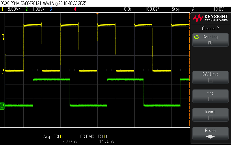
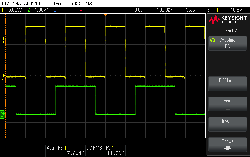
This allows me to look at the PWM waveform and The ADC sampling time on a scope.
(In this experiment, I’ve reduced the PWM frequency to 5kHz to be sure that it was always centered)
Depending on the initialization delays, The ADC seems to be sampled on the High side mid-point of the PWM (when the low side mosfets are not conducting, thus the 0A measurements.
I’ll try to investigate more, I’m not very familiar with STM32 peripheral so it might take some time. Is there a doc on the intended PWM and ADC setup for SimpleFOC?
Huh this might be a new issue introduced in the v2.3.5.
Could you maybe try the v2.3.4?
The pwm driver is rewritten from 2.3.4 to 2.3.5. I’ve updated the sync on all the stm32 architectures but I’ve just seen that I forgot the bg431 hardware specific code!
Basically these lines:
Should be:
If this is the issues, we will patch this ASAP.
But the easiest way to avoid the issue is to use the v2.3.4.
EDIT:
As a short explanation. In the earlier versions of the library we stopped the timers entirely when syncing the driver and the ADC. But from the v2.3.5 we are only pausing it. So it’s current state can be upcounting or downcounting, while before it was always starting with the up-counting (because it was stopped before). So till 2.3.5 we did not need to verify the counting direction before choosing how to downsample. From v2.3.5 we need to see in which dir did we stop the timer. And the bg431 code was not updated so sometimes it downsamples well (by chance) reading the low-side, and sometimes (if the magical delay is added) it samples the high side.
I’ve updated the code fixing the issue. I unfortunately do not own one of these boards so I would appreciate it if you could test. Or someone else from the community if they are motivated
Just for my clarity: what works now is Antun‘s fix for the ADC Timer Sync, but the fast UART problem remains? Or the ADC Timer Sync problem was causal also for the fast UART issue?
Yes, The UART was not really the problem, it just affected the time of initialization by changing the debug print duration. The synchronization of the ADC wrt PWM had a 1/2 chance of being out of phase depending on when it was called. Long story short, with Antun‘s fix, the adc is always in sync, and I can use UART at any baudrate without issue;
Just for my clarity: what works now is Antun‘s fix for the ADC Timer Sync, but the fast UART problem remains? Or the ADC Timer Sync problem was causal also for the fast UART issue?
– rungerYes, The UART was not really the problem, it just affected the time of initialization by changing the debug print duration. The synchronization of the ADC wrt PWM had a 1/2 chance of being out of phase depending on when it was called. Long story short, with Antun‘s fix, the adc is always in sync, and I can use UART at any baudrate without issue;
– thomasfla