Hi all.
I have an IHM08M1 motor driver.
I would like to know how I could use the simple FOC library with it.
It does not have an enable pin and for each phase it has two pins (High and Low).
Thank you very much.
Hi all.
I have an IHM08M1 motor driver.
I would like to know how I could use the simple FOC library with it.
It does not have an enable pin and for each phase it has two pins (High and Low).
Thank you very much.
SimpleFOC had not supported, but it will support in future accroding to its roadmap. I have asked the same question before.
Hey guys,
I am confident that the next version library release will have this feature integrated.
The problem of this approach is that it very very hardware specific.
Not each MCU will be able to do it, so I need to figure out a way to integrate this safely to the library.
The other problem of this approach is that if you don’t implement it well you can burn the transistors. Therefore I feel obligated to do extensive testing before publishing such a code. 
If someone has actually used ESP32 or STM32 boards with 6pwm modes plase dont hesitate to contact me and share the code. It will help a me a lot to integrate it quicker to the library.
@Antun_Skuric, that sounds good, I have made a MP6540 test board that it is suitable for testing 6pwm mode. I can test it 2 or 3 days later.
I connnected this board to STM32 bluebill board, can you send me the file for testing 6pwm mode, thanks.
I don’t have any code to help. 
But would like to help test. I’ve got a hoverboard controller in need of 6pwm!
Happy to test alpha code with understanding that boards may get damaged until all bugs are ironed out.
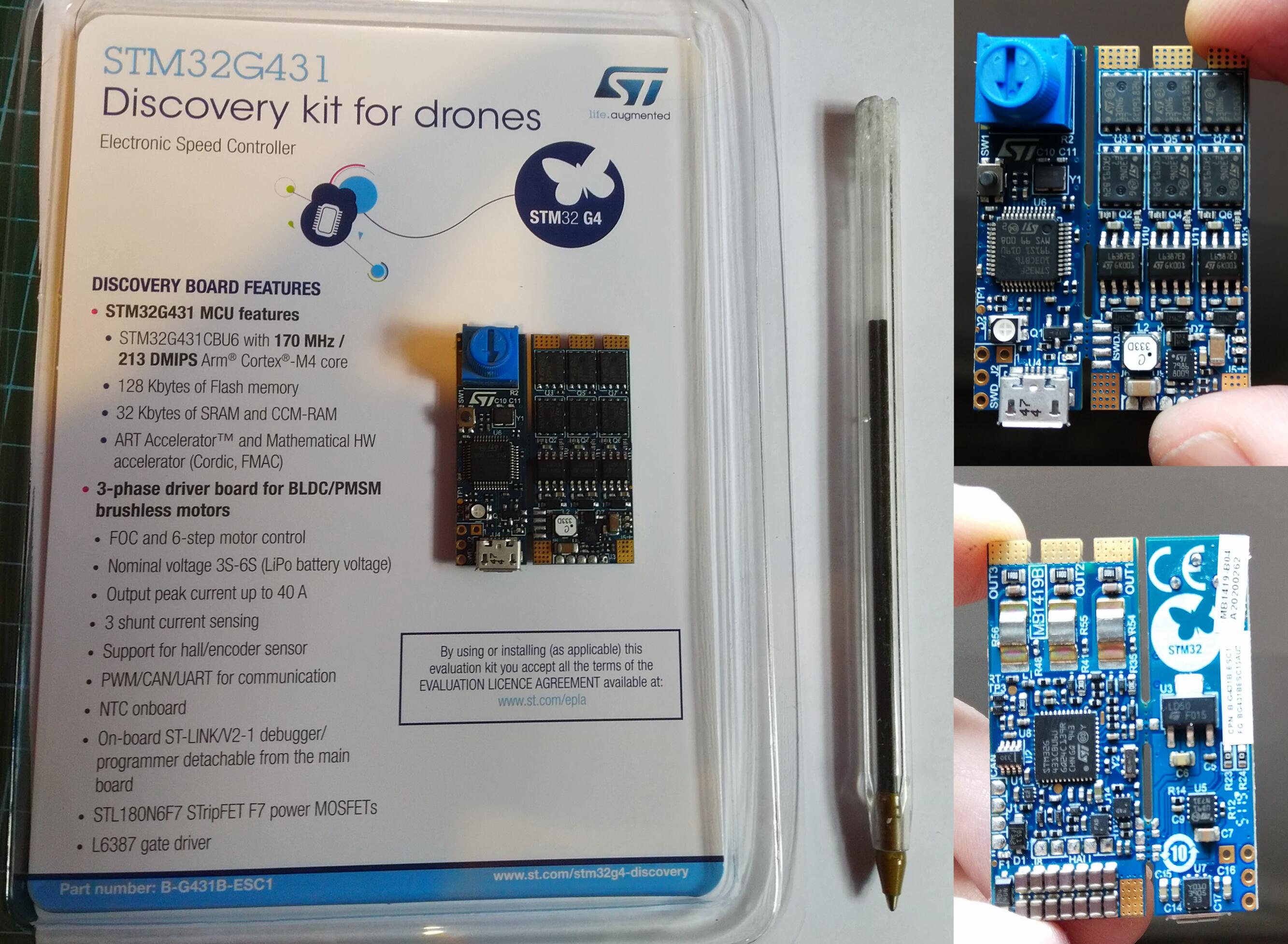
Update: Just received an STM32G431. It has 3 L6387 drivers that are similar to the L6398 in the bigger IHM08M1. This will be easier to test than the hoverboard.
Another chip that already has 6pwm and other advanced features and pretty low cost is the STSPIN32F0A.
Hey @Owen_Williams,
Did you try to program this board with Arduino IDE?
Is the onboard stm chip supported by the stm32duino?
It’s remained in its box. Unloved
I’ve pulled it out to see if I can at least flash to it. Platformio supports a couple of devices with the stm32g431 but there isn’t an exact match for this board. The nucleo_g431rb board is close enough for an upload to work.
If you are asking from a 6pwm development perspective - its possibly ok for openloop experimentation. There is no i2c, spi pins and Serial.println() won’t work unless you solder up an ftdi to rx/tx. I could look into it further if you like.
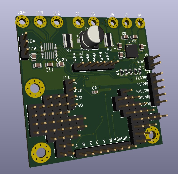
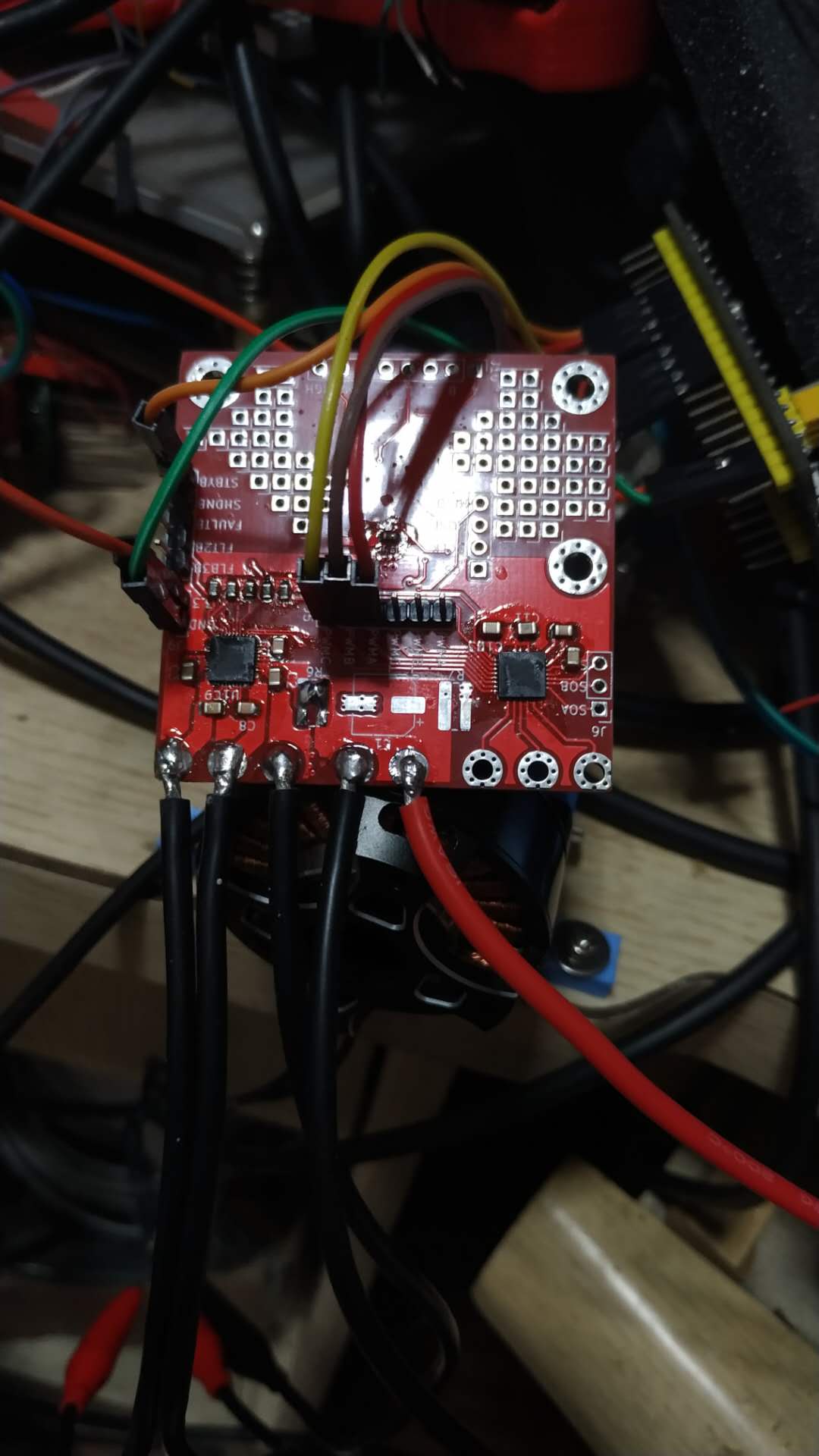
I’ve dug out my STM32G431 discovery kit for drones after @MrAnderson reminded me that it has an opamp on it. I’d forgotten it had current sensors on the back! The datasheet is worth a read if you are into 6pwm or shunt resistors.
I got put off using this kit last month because it can only be controlled through 6PWM and simplefoc doesn’t support 6pwm yet. I spent an hour tonight and knocked up some simple code to do 6 step commutation as per page6 of this stm application note.
A quick 2 minute video:
")
And the very simple code (not yet using simplefoc) that I used in the video
#include <Arduino.h>

#define STATUS_LED PC6
#define POT PB12

#define TX PB3
#define RX PB4

#define MOT1_OUT_H PA8
#define MOT2_OUT_H PA9
#define MOT3_OUT_H PA10
#define MOT1_OUT_L PC13
#define MOT2_OUT_L PA12
#define MOT3_OUT_L PB15

#define MOT1_SENSE_H PA1
#define MOT2_SENSE_H PA7
#define MOT3_SENSE_H PB0
#define MOT1_SENSE_L PA3
#define MOT2_SENSE_L PA5
#define MOT3_SENSE_L PB2


HardwareSerial Serial1(RX, TX);

int duty_cycle = 80;

void setup() {
  Serial1.begin(115200);

  pinMode(MOT1_OUT_H, OUTPUT);
  pinMode(MOT2_OUT_H, OUTPUT);
  pinMode(MOT3_OUT_H, OUTPUT);
  pinMode(MOT1_OUT_L, OUTPUT);
  pinMode(MOT2_OUT_L, OUTPUT);
  pinMode(MOT3_OUT_L, OUTPUT);

  pinMode(STATUS_LED, OUTPUT);
  pinMode(POT, INPUT);
}

void setPWM(int m1_h, int m2_h, int m3_h, int m1_l, int m2_l, int m3_l) {
  Serial1.printf("%d\t%d\t%d\t%d\t%d\t%d\t", m1_h, m2_h, m3_h, m1_l, m2_l, m3_l);
  analogWrite(MOT1_OUT_H, m1_h);
  analogWrite(MOT2_OUT_H, m2_h);
  analogWrite(MOT3_OUT_H, m3_h);
  analogWrite(MOT1_OUT_L, m1_l);
  analogWrite(MOT2_OUT_L, m2_l);
  analogWrite(MOT3_OUT_L, m3_l);
}

void steps(int delayMillis) {
  digitalWrite(STATUS_LED, HIGH);

  setPWM(duty_cycle, 0, 0, 0, duty_cycle, 0);
  Serial1.println("M2- M1+");
  delay(delayMillis);

  setPWM(duty_cycle, 0, 0, 0, 0, duty_cycle);
  Serial1.println("M1+ M3-");
  delay(delayMillis);

  setPWM(0, duty_cycle, 0, 0, 0, duty_cycle);
  Serial1.println("M3- M2+");
  delay(delayMillis);

  digitalWrite(STATUS_LED, LOW);
  setPWM(0, duty_cycle, 0, duty_cycle, 0, 0);
  Serial1.println("M2+ M1-");
  delay(delayMillis);

  setPWM(0, 0, duty_cycle, duty_cycle, 0, 0);
  Serial1.println("M1- M3+");
  delay(delayMillis);

  setPWM(0, 0, duty_cycle, 0, duty_cycle, 0);
  Serial1.println("M3+ M2-");
  delay(delayMillis);

}

int step = 0;

void loop() {
  int pot = analogRead(POT);
  int delaySpeed = map(pot, 0, 1023, 10,500);
  Serial1.println();
  Serial1.print("delay: ");
  Serial1.println(delaySpeed);

  steps(delaySpeed);
}
I coded in platformio using nucleo_g431rb board variant. Not sure if this is also available in arduino IDE. What I don’t know and will have to research is how to safely use 6PWM with proper foc. I suspect the stm32 can be put in some pwm synchronised mode. Phase 1+ pin output is using TIM1_CH1 and Phase 1- is using TIM1_CH1N - so I’m guessing this is a clue as to how to eNsure the stm32 doesn’t open high/low gates at the same time.
Hi Owen,
what exactly do you mean with 6PWM? Do you mean the basic 6 step block commutation per electrical cycle?
Or does it mean, that either the high and the low parts of the h-bridges are controlled by independend PWM signals? If so, how do you ensure that the highside and lowside mosfets of the bidges are controlled in “mirror-inverted” matter? (rectified synchronization)
And please excuse one more question.
I really like those fancy beeps of the motors (e.g. when arming drones). It seams like you are the professional here. Can you explain how do you do that? How the pitch of a tone is controlled etc?
By 6PWM - I mean the latter. SimpleFOC only works with 3PWM pins currently. You can see that from the fact that BLDCMotor constructor only takes 3 pwm args. The driver on my g431 discovery kit is a L6377 and requires 6pwm control.
Currently my code above is effectively jumping 60 electrical degrees each step. I think this is call 6 step commutation, but that term might refer to reading hall sensors. Hope you know what I mean.
In my code above the 6step commutation naturally has an interstitial step where both high and low for a phase is zero e.g. a phase doesn’t go from high to low directly but moves through both high and low being off. If you are still confused take a look at page 6 of the link I posted.
Re. fancy beeps, I wrote a library recently for making tones with SimpleFOC. I may need to change it as I think motor.setPhaseVoltage() might have changed to be private. I’ve been meaning to move it over to simplefoc.
Next step is moving away from this square wave 6 step to sinusoidal with SimpleFOC and yes - I’m wondering the same as to how to avoid short circuiting high and low. I think @Antun_Skuric has already said that the solution is likely to be very hardware dependent e.g. using specific timer features that I know very little about. I’m going to try to do a dumb software approach first.
I think I’ve found something interesting about the l6387 drivers in my g431 kit for drones and the l6398 drivers in the @Francesc_Riera_Vidal (original poster) Nucleo IHM08M1 board. It looks as if they both offer protection from short circuiting low/high gates. Can someone who knows electronics better than me confirm that the following means I can accidentally hold VIN and LIN active without damaging anything:

And to the uses a L6398 driver which, I believe implies the same:

It’s a bit harder to read because LIN is active low.
If this is right, it means that getting 6PWM support for these particular drivers should be straightforward!
Which stm32 have on it? I have an a https://www.st.com/en/evaluation-tools/evalkit-robot-1.html
and its using 6PWM but this is done on internally on the STSPIN32F0A
There are some project files for FOC on the STM32 as part of the evalkit robot 1
So you understood that we only need to apply the same output signal for the LIN and HIN pin.
Since the LIN is reversed.
Thank you very much for the info.
I answer to myself.
I found this in the l6398 datasheet.
(*) HIN and LIN can be connected togheter and driven by just one control signal.
Hi, @Owen_Williams I wonder if sfoc support g431 discovery kit now? I want to desing my own pcb with stm32g431cbt6. However, it seems that stm32duino just support g431rb and g431kb. Its more convenient and cheap for me to use cbt6.
I guess you know that the c means 64 pins. This is the same number of pins as the b-g341b-esc1. I would imagine that the board variant i created (that is due to be merged soon) will be similar to what you need. If you choose the same hse speed then that would help. If you copied the pin usage e.g used the same pins for 6pwm and current sense you could probably use the same board variant.
That’s really a good news