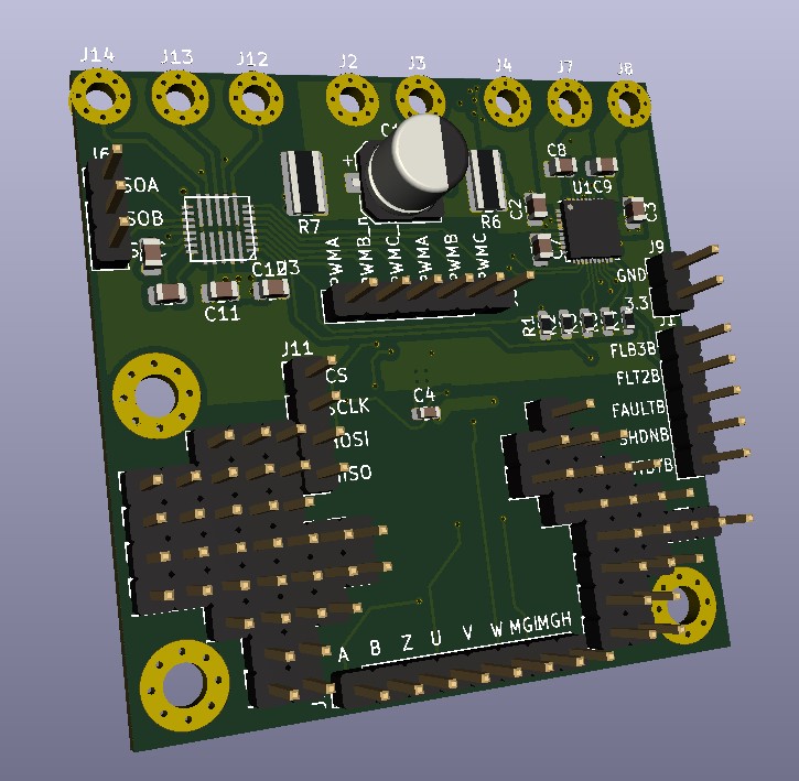
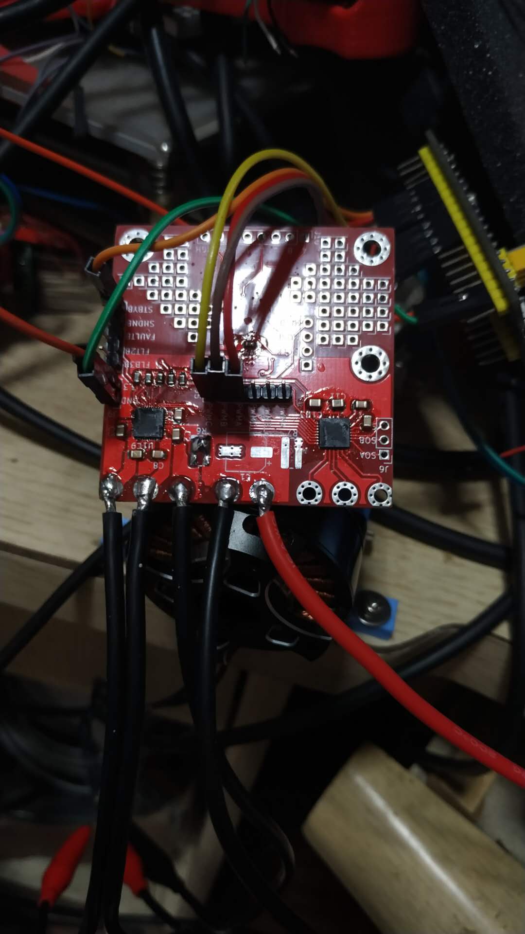
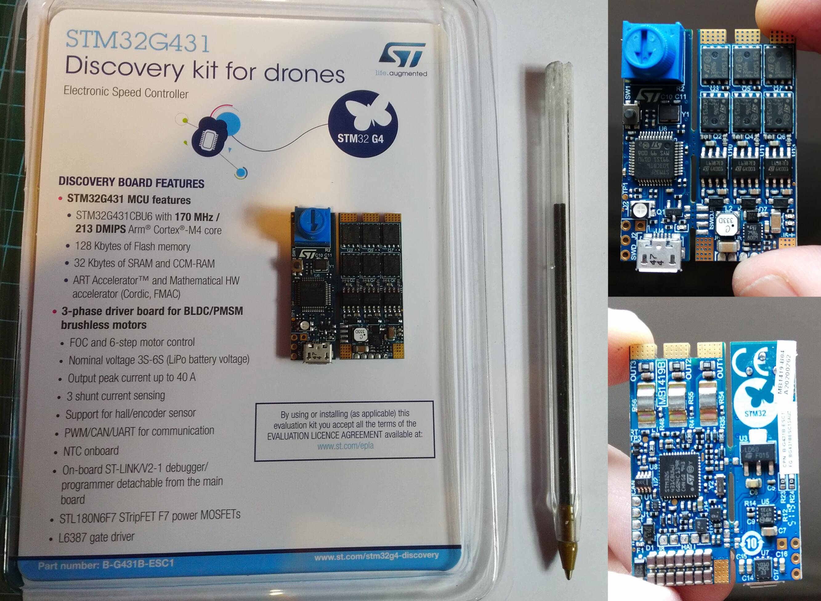
I’ve dug out my STM32G431 discovery kit for drones after @MrAnderson reminded me that it has an opamp on it. I’d forgotten it had current sensors on the back! The datasheet is worth a read if you are into 6pwm or shunt resistors.
I got put off using this kit last month because it can only be controlled through 6PWM and simplefoc doesn’t support 6pwm yet. I spent an hour tonight and knocked up some simple code to do 6 step commutation as per page6 of this stm application note.
A quick 2 minute video:
And the very simple code (not yet using simplefoc) that I used in the video
#include <Arduino.h>

#define STATUS_LED PC6
#define POT PB12

#define TX PB3
#define RX PB4

#define MOT1_OUT_H PA8
#define MOT2_OUT_H PA9
#define MOT3_OUT_H PA10
#define MOT1_OUT_L PC13
#define MOT2_OUT_L PA12
#define MOT3_OUT_L PB15

#define MOT1_SENSE_H PA1
#define MOT2_SENSE_H PA7
#define MOT3_SENSE_H PB0
#define MOT1_SENSE_L PA3
#define MOT2_SENSE_L PA5
#define MOT3_SENSE_L PB2


HardwareSerial Serial1(RX, TX);

int duty_cycle = 80;

void setup() {
  Serial1.begin(115200);

  pinMode(MOT1_OUT_H, OUTPUT);
  pinMode(MOT2_OUT_H, OUTPUT);
  pinMode(MOT3_OUT_H, OUTPUT);
  pinMode(MOT1_OUT_L, OUTPUT);
  pinMode(MOT2_OUT_L, OUTPUT);
  pinMode(MOT3_OUT_L, OUTPUT);

  pinMode(STATUS_LED, OUTPUT);
  pinMode(POT, INPUT);
}

void setPWM(int m1_h, int m2_h, int m3_h, int m1_l, int m2_l, int m3_l) {
  Serial1.printf("%d\t%d\t%d\t%d\t%d\t%d\t", m1_h, m2_h, m3_h, m1_l, m2_l, m3_l);
  analogWrite(MOT1_OUT_H, m1_h);
  analogWrite(MOT2_OUT_H, m2_h);
  analogWrite(MOT3_OUT_H, m3_h);
  analogWrite(MOT1_OUT_L, m1_l);
  analogWrite(MOT2_OUT_L, m2_l);
  analogWrite(MOT3_OUT_L, m3_l);
}

void steps(int delayMillis) {
  digitalWrite(STATUS_LED, HIGH);

  setPWM(duty_cycle, 0, 0, 0, duty_cycle, 0);
  Serial1.println("M2- M1+");
  delay(delayMillis);

  setPWM(duty_cycle, 0, 0, 0, 0, duty_cycle);
  Serial1.println("M1+ M3-");
  delay(delayMillis);

  setPWM(0, duty_cycle, 0, 0, 0, duty_cycle);
  Serial1.println("M3- M2+");
  delay(delayMillis);

  digitalWrite(STATUS_LED, LOW);
  setPWM(0, duty_cycle, 0, duty_cycle, 0, 0);
  Serial1.println("M2+ M1-");
  delay(delayMillis);

  setPWM(0, 0, duty_cycle, duty_cycle, 0, 0);
  Serial1.println("M1- M3+");
  delay(delayMillis);

  setPWM(0, 0, duty_cycle, 0, duty_cycle, 0);
  Serial1.println("M3+ M2-");
  delay(delayMillis);

}

int step = 0;

void loop() {
  int pot = analogRead(POT);
  int delaySpeed = map(pot, 0, 1023, 10,500);
  Serial1.println();
  Serial1.print("delay: ");
  Serial1.println(delaySpeed);

  steps(delaySpeed);
}
I coded in platformio using nucleo_g431rb board variant. Not sure if this is also available in arduino IDE. What I don’t know and will have to research is how to safely use 6PWM with proper foc. I suspect the stm32 can be put in some pwm synchronised mode. Phase 1+ pin output is using TIM1_CH1 and Phase 1- is using TIM1_CH1N - so I’m guessing this is a clue as to how to eNsure the stm32 doesn’t open high/low gates at the same time.

")

