True, the hoverboard format does have a good format for your machine, so if you can g’et one with the appropriate resistance/amp rating @around peak 10amp ![]()
![]()
Yeah, I think this is the case. I’m no expert on magnets, but the permanent magnets in BLDC motors are used up well into the KW range, with motors using 100s of Amperes. The BLDCs are designed by their nature to operate in an alternating magnetic field, with the currents in the windings changing directions all the time. I’ve never heard of a current demagnetisation problem, but perhaps I’m just not aware of it, because the motors I use are much smaller.
Certainly for a drone type motor you don’t have to worry about it.
What you do have to worry about is heat. The motors with low resistance can draw huge currents quickly, much more than they can permanently withstand. And high resistance motors heat more slowly, but can still overheat if left stalled for too long.
The magnets in the motors start to demagnetise between 80° and 110°C, depending on their quality. So it depends how quickly the motor heats - if you’re passing 200A, the winding insulation will melt or evaporate, or the windings themselves will disappear in a cloud of smoke. But if its just 20A, then the winding insulation may very last a long time, and the whole motor can heat up to 100° or more, becoming burning hot to touch and demagnetising its permanent magnets.
In FOC you use all three phases all the time. You don’t switch one of them to the high impedance state. Using 6-step or block commutation after computing the correct current vector would “discretize” it, and could not represent it as accurately as the sine waves can.
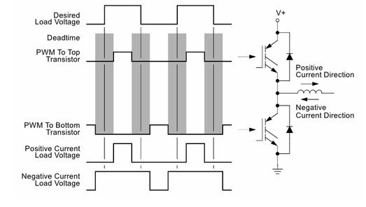
It’s not actually so complicated: the three motor phase voltages are encoded in the PWM duty cycle, and output to the driver hardware. If switching the FETs independently (6-PWM) the MCU has to produce complementary PWM signals for the high and low side FETs, and the only complication is the “dead-time”: to account for the switching times of the FETs and ensure the half-bridge is never short-circuited, the complementary PWM signals need to include a small delay beween the switch-off and the switch-on events, to give the FETs enough time.
Oh, that is a quite low temperature. I was not aware, that these magnets were that sensitive. Thanks for the advice. It made me search a bit more information of this subject, and found this:
https://www.magnetexpert.com/technical-advice-for-every-application-magnet-expert-i685/temperature-effects-on-magnets-i683
It states, that ordinary brushed DC motors often got the older type ferrite magnets, that can withstand higher temperatures. I guess many of this kind of DC motors I know would have been damaged otherwise.
I tried to study this matter a bit more, and it seems that for instance the STM32 got timers that are well suited for that. I looked this video that provide the basic FOC idea:

Within a electrical sector of 60 degrees you got 6 (or 7) states and 4 output patterns, and the timing of the 4 patterns can be made with a PWM timer and three compare registers. The rest is simple logic and the “dead-time” issue, that you points out.
This previous answer do also provide information:
https://community.simplefoc.com/t/stm32f446-which-timers-are-used-by-simplefoc/1570
Interesting discussion!
Yes, you are right. But this type of space vector switching is not what SimpleFOC does. This is more common in VFD drives for industrial equipment and maybe EVs, but not typically the way it’s done in smaller FOC solutions.
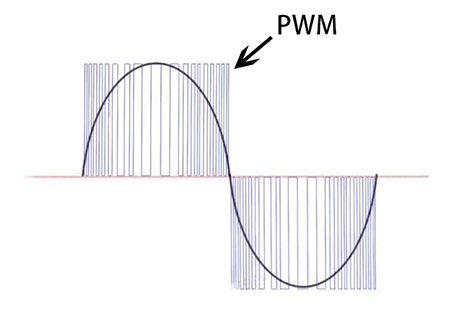
In the switching scheme as shown in the video the phases are switched in a coordinated way. But SimpleFOC employs the PWM to drive a sine wave to the phases, and each phase is switched completely independently. While we make effort to align the timers, this is for other reasons (to do with the current sensing), and in fact on most of our hardware drivers I think you can choose the pins pretty freely, and if there is a timer on the pin then SimpleFOC will use it. So it’s definately possible to end up with PWM signals that are not aligned, possibly not even the same frequency, and you will still get working commutation.
This is because the PWM just drives the sine wave, and the position of the three sine waves with respect to the rotor angle determines the angle of the current vector. (inverse Park/Clarke transform).
(image from inverter.com)
Thanks again for explaining. A lot of documents and presentations provide the same information about space vector modulation as given in this video above. Then I just assumed with no knowledge, that FOC always would mean that method. Thanks to you, I now know better. I guessed, that independent switching of the half bridges would lead to not working chaos, but apparently, it is not the case.
I tried to work with a timing diagram with the SimpleFOC way, when you use the same timer with three compare registers. Then I looked at a situation with a very slow running motor, with like the same voltage vector applied. One is the base vector situation with phase R at about half voltage and phase S and T will be a quarter voltage negative. It looks like this:
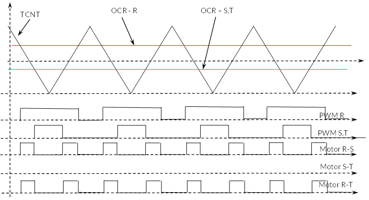
If you look at the same situation with the space vector implementation in video, you get exactly the same pattern.
Now you can try to move 30 degrees away from a base vector. Then it looks like this (a bit higher voltage here):
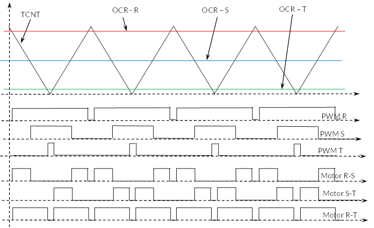
And then you can compare to the pattern of the space vector way, and again you get exactly the same. Perhaps it is just two different ways to implement or think about it, and they provide the same result.
I also noticed this video talk about difference in Space Vector PWM and Sinosoidal PWM and I jump to right place in video:

It seems to me, that it will also be possible in the SimpleFOC way to introduce non sinosoidal values to the compare registers in some way, and thereby provide the max possible output sine wave voltage to the motor.
SimpleFOC does support SpaceVectorPWM as a modulation type, for exactly the reason you mention.
I have tried to do an estimate calculation with a stepper motor. In order to achieve the 2000 rpm, I should base the mechanics to have direct drive on the sewing machine. Then I looked for a stepper motor with at least 3.5 Nm torque. This could be one:
https://www.ebay.com/itm/225502210457
It got a nominal current of 4 Amps, 200 steps each rotation and 4.5 Nm holding torque and about 4.5 mH self inductance each coil.
Assume that you run this motor at 2000 rpm. Then the step frequency of the windings will be 6.67 kHz. At this frequency the reactance of the windings will be 188 ohm. At this speed you need 0.7 Nm and for this you need at least double holding moment of 1.4 Nm. This will require a current of 1.2 Amp. So you will need a voltage of about 230 V 6.67 kHz on windings just to keep this current before you know what the EMF from motor would be. I therefore find this approach with this stepper motor unrealistic and quite far from something realistic.
Did I do some wrong calculations here?
Custom hover-motor? @around peak 10 amp ?
You need around 2000rpm/48v = 42KV
“Custom hover-motor” - something custom made just sound like “expensive motor” to me. Why should a standard inexpensive motor not work?
Above I tried to make a calculation on one of the proposed motors of this website here:
https://docs.simplefoc.com/bldc_motors
I shall now try to estimate the use of one a bit more expensive motor called ML4114 330KV. I found it for sale here. It might be an old kind, because more sellers stopped selling it:
https://brushlessgimbal.ca/Multi-Rotor-Products-Parts/Brushless-Motor/GARTT-ML4114-330KV-Brushless-Motor
This link provided more data:
https://vi.aliexpress.com/item/1005005222664408.html
At full power condition at 25.2 Amp it consumes 564 W. The resistive loss in windings should be about 70 W. However I think the rise of temperature and other losses might double this loss figure to 140 W. Therefore I estimate shaft power of 564 - 140 W = 424 W and at 5090 rpm. Then the max torque at this current should be 0.80 Nm. Then the gearing should be of 3.5:0.8 = 1:4.4.
The max speed of sewing machine at 2000 rpm would require 8800 rpm. 22.2 V x 330 kv = 7326 rpm. It is close, but not quite there with this motor.
Perhaps you could accept a higher current short term. If you assume a max speed of 6500 rpm with a shaft power of 140 W, then the gearing should be 1:3.25. The short term motor torque would then be 1.08 Nm and the short term current. 34 Amp. The mean torque of 1.2 Nm on machine should cause a current of 12 Amp, and this current may be all right for thermal considerations. It should cause resistive loss in windings of 16 W.
I guess this kind of motor should manage the job. Do you agree?
I suppose that is relative. Isn’t it a prototype?
Perhaps @runger you could bring it up with the board, regarding 68100 or 6875/6850 with a low KV for the SFOC shop. With a low peak amp rating around 10-15 amp or so. Can have many uses and will stand out as a unique product. Perhaps battle hardened…
Maybe a kit for DiY winding…
No, not regarding the design of the motor, if it can be avoided. Why should you suggest a custom motor, if a standard relative cheep motor can do the job?
There is other considerations here regarding the good and fast low speed control and resistance to load changes, and this aspect might be considered prototype, because this is not a normal requirement for these electrical motors.
Curious, what is your need for BEMF measurement? That is what seems to be holding you back from using other motors, and like mentioned earlier, simpleFOC does not support any BEMF sensing, and you can certainly get along at 2k RPM with many magnetic encoders, hall sensors, optical encoders, etc.
I do not need BEMF measurement or some way to measure speed without another sensor. I asked about it, because it would just be easier to avoid it, and I have seen a few amazing videos of some developers of motor drives, that could do it.
I started to write, that I am working on using a brushed DC motor, and I think they can do the job, when you use some speed feed-back. So yes, I do try other solutions. At the moment I use a tiny brushed DC motor as a Tachogenerator to provide speed feed-back, at it works very well, and it is a cheep solution.
But I am not sure about the durability of the brushes. Therefore I also look a bit into other possibilities.
The digital encoders with about 1000 lines is not that attractive for me for two reasons. One is price. The other is, that it got issues at low speed and high speed. Assume the use of the ML4114 motor. At high speed of about 7500 rpm you should have a encoder frequency of 125 kHz or about 8 us between each rising edge on one sensor. It just seems a bit demanding to make a measurement of period time here, and it might be to the limit of what the encoder can manage. How much do the time period vary between too rising edges at a constant high speed and at some lower speed?
At low speed you have about 30 rpm on motor. Then you will have 500 pulses each second or one possible speed reading each 2 ms. But my measurements with the DC motors indicate, that you get a better control of speed if you can measure speed every 0.5 ms or perhaps each 1 ms.
Analog hall elements may be able to do it, but it will also depend of the noise you got in the field signal. At 30 rpm and 0.5 ms time the rotor moves only 0.09 degrees. Can you detect that change with a good resolution?
A small brushed DC-motors used as Tachogenerator are an excellent sensor for such a job. It can keep a low speed stable on a cheap 20000 rpm DC motor down to 6 rpm.
With SpaceVector PWM, you get an output voltage of 1.15 higher voltage to the motor with same number of cells and electronics except software. When motors are defined with their KV-value - do they refer to SpaceVector PWM or to Sinosoidal PWM?
AFAIU, the kV rating is determined just by measuring measuring the rpm of the shaft when the BEMF produced on the windings is 1 volt p-p on a phase. It doesn’t make sense to make any sort of note about control signal modulation as you are not controlling the motor.
SVPWM does not actually increase the supply / “output” voltage, it just increases the relative voltage between the windings so that the effective bias on the motor is larger.
It makes sense, that the motor manufacturer will base their KV-value on that. I think you mean that KV is the rpm, that will produce a BEMF of one volt peak and two volts peak-peak on two terminals of the motor when driven by another motor. Do we agree?
What matters is what kind of maximum sinus voltage that the motor will get between two of its terminals. This sinus peak voltage is 1.15 times higher with SVPWM than with Sinusoidal PWM.
When I read this comment by runger:
Then SimpleFOC makes a sinus voltage on each individual phase. This is Sinosoidal PWM. With SVPWM each individual phase do not provide a sinus voltage.
Therefore you can drive a motor at higher speed with SVPWM than with Sinosoidal PWM. Therefore I think that this distinction do matter.
I think you are too far in the weeds for not having any sort of prototype… please read the docs, both SinePWM and SpaceVectorPWM are supported modulation types.
First - I am in no hurry for this, so I do not need to start on a prototype with these motors before I know more. I do also like to harvest the information from the the brushed DC motor design before I moving on.
I think you are right, that SVPWM is supported by SimpleFOC. I just trusted you and runger ![]() I found the information further down some links:
I found the information further down some links:
At least I found some possible standard BLDC motors now, that should be able to handle loads. It seems to me, that I end up with a needed short term peak current between 30 and 40 Amp to motor and somewhat less from the 24 VDC supply. So I should look for some ESC hardware able to handle that.
I consider two BLDC motors able to meet the specifications for this sewing machine:
- Tarot 6S 3515 Kv400
https://www.aliexpress.com/item/1005006341824522.html
Price: 29+5 euro
This is some of the important specifications:
Maximum continuous current: 28.4A
Maximum continuous power: 630W
Internal resistance: 85mΩ
Motor weight: 142g
One load condition is:
Speed: 6893 rpm
Voltage: 22.2 V
Current: 24.5 A - estimates this provides 0.61 Nm.
When I make calculations on these specs, then I estimate this situation:
24 VDC supply
Gearing to sewing machine: 1:4.7
Short term max current: 29.4 Amp
Current in some longer periods: 10 Amp (thermal value)
- Gartt ML 4114 330KV
https://www.aliexpress.com/item/1005006341806558.html
Price: 40 + 0 euro
Motor Resistance (RM): 0.1082 Ω
Max Continuous Current : 25A
Max Continuous Power: 750W
Weight ≈170g/6oz
Lipo Cell : 4S~8S
One load condition is:
Speed: 5090 rpm
Voltage: 22.2 V
Current: 25.4 A - estimates this provides torque of 0.8 Nm
When I make calculations on these specs, then I estimate this situation:
24 VDC supply
Gearing to sewing machine: 1:3.7
Short term max current: 30 Amp
Current in some longer periods: 10.5 Amp (thermal value)
I looked at that simpleFOC recommend some drivers here:
One of them is this STM discovery kit that includes an STM microcontroller
https://www.st.com/en/evaluation-tools/b-g431b-esc1.html
Can the simpleFOC be loaded to this kit and use it?
Can you have the encoder inputs as you want?
Do you think this kit is a suitable driver for the motors above?