Hello everyone,
I am using a bldc motor with the simpleFOCmini in order to compress a spring.
At some point in my use case, the spring must be released. This can happen in the case of a maximal compression. The potential energy of the spring is converted in kinetic energy. This kinectic energy transforms into electric energy due to back-emf (from my understanding).
I do release the spring by disabling the motor (from the code : m_motor->disable). This must leave the mosfets of DRV8313 open or floating (?)
I killed a powerbank while releasing the spring at his max compression.
The powerbank is either a source or a sink, it should have not like having current flowing while being a source.
I then tried with a lab supply and monitored.
I first wanted to see how it works with the supply off. I can set the condition with tools. I couldn’t see much, 1V (voltage level between + and - of the supply).
Then with supply on, it strarts at 16V (nominal voltage of motor) and reach 32V ! at max during the energy transfert.
My guess is that when I do it with power supply off, the bulk capacitor of the driver absorbs most of the EMF. But when i do it with the supply on, the capacitor is already charged and cannot absorb ?
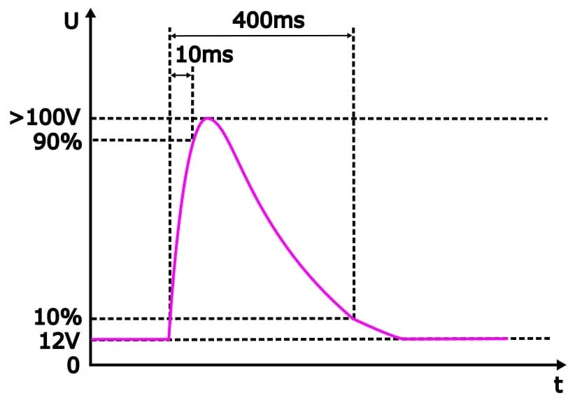
The shape of the voltage over time during release looks like “load dump” (even if it isn’t technically).
I first expected that the current generated by the motor will be absorbed by the battery. But the voltage levels scared me and searches on internet and this forum conviced me that it is not that simple.
EDIT : I found the courage to experiment it with a battery pack that I knew had little safety (bosch 18V). The voltage do not raise as in the case of the lab supply. The bidectionnal behavior of the battery might be the reason.
I use a 16V,2A nominal motor.
My questions is:
- What kind of schematic would be easy to implement in order to protect the battery from overvoltage ?
Sincerely,