Hi,
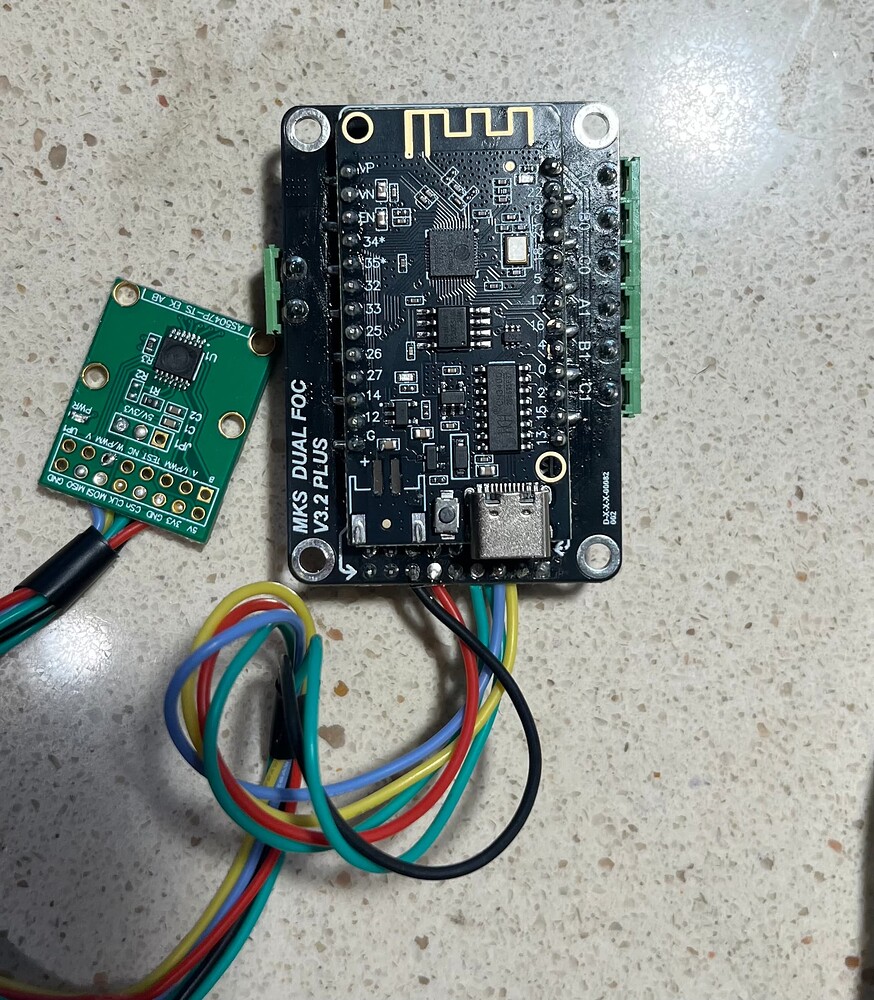
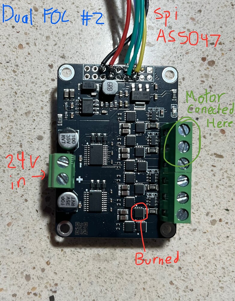
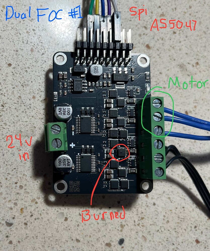
I have a set up consisting of a GM3506 gimbal motor with a MKS Dual FOC plus driver. Ive had issues with two separate boards burning up when driving a motor through the second driver with current torque control.
I had torque control working properly through the first driver(with a bit of jitter when holding position) but I ran into a severe issue when testing that same torque control mode with the second driver on the MKS board(A1,B1,C1). In the code the first driver is not enabled so the pins are left floating, but the second driver is properly enabled. And when I run the code and do some tests the MKS board burns out and then pulls 10Amps or so from the power supply. Ive had that happen with two separate boards. I am not sure what the issue is but I think it make be something with the first driver left floating.
Set up: I am driving the MKS Dual FOC plus board at 24 volts with a motor voltage limit of 12V. I am using the esp32 chip that comes with the Dual FOC board. The Gimbal motor has a resistance of 5.6Ω. The set up works if I’m driving the motor with the first driver, but if I switch to the second driver then the driver burned out


#include <Arduino.h>
#include <SimpleFOC.h>
// BLDC motor & driver instance
BLDCMotor motor = BLDCMotor(11);
//BLDCDriver3PWM driver = BLDCDriver3PWM(32, 33, 25, 22); ///MKS esp32
BLDCDriver3PWM driver = BLDCDriver3PWM(26, 27, 14, 12); //MKS esp32 // SECOND DRIVER (One with problem)
MagneticSensorSPI sensor = MagneticSensorSPI(AS5147_SPI, 5);
//MagneticSensorSPI sensor = MagneticSensorSPI(AS5147_SPI, 15);
// current sensor
//InlineCurrentSense current_sense = InlineCurrentSense(0.01f, 50.0f, 39, 36); //MKS esp32
InlineCurrentSense current_sense = InlineCurrentSense(0.01f, 50.0f, 35, 34); //MKS esp32 // SECOND DRIVER (One with problem)
float target_angle = 0;
float target_velocity = 0;
float current_limit;
unsigned long flagTime;
int flag = 1;
// instantiate the commander
Commander command = Commander(Serial);
/*
void doTarget(char* cmd) {
command.scalar(&motor.target, cmd);
}
*/
void doTarget(char* cmd) {
command.scalar(&target_angle, cmd);
}
void currentLim(char* cmd) {
command.scalar(¤t_limit, cmd);
motor.current_limit = current_limit;
motor.PID_velocity.limit = motor.current_limit;
}
void setup() {
// initialize encoder sensor hardware
sensor.init();
// link the motor to the sensor
motor.linkSensor(&sensor);
// driver config
// power supply voltage [V]
driver.voltage_power_supply = 24;
driver.voltage_limit = 24; // max voltage to motor
driver.init();
// link driver
motor.linkDriver(&driver);
// link the driver to the current sense
current_sense.linkDriver(&driver);
// current sense init hardware
current_sense.init();
current_sense.gain_b *= -1;
// link the current sense to the motor
motor.linkCurrentSense(¤t_sense);
motor.foc_modulation = FOCModulationType::SpaceVectorPWM;
// set torque mode:
motor.torque_controller = TorqueControlType::foc_current;
motor.current_limit = .5; // Amp limit
// set motion control loop to be used
//motor.controller = MotionControlType::torque;
//motor.controller = MotionControlType::velocity;
motor.controller = MotionControlType::angle;
/*
// foc current control parameters (Arduino UNO/Mega)
motor.PID_current_q.P = 5;
motor.PID_current_q.I = 300;
motor.PID_current_d.P = 5;
motor.PID_current_d.I = 300;
motor.LPF_current_q.Tf = 0.01;
motor.LPF_current_d.Tf = 0.01;
*/
/*
motor.PID_current_q.P = 2; //修改合适的PID参数以实现更好的效果
motor.PID_current_q.I = 800; //电机出现抖动、转速不稳定的情况,很有可能就是PID参数没调到合适的
motor.PID_current_d.P = 2;
motor.PID_current_d.I = 800;
motor.LPF_current_q.Tf = 0.002; // 1ms default
motor.LPF_current_d.Tf = 0.002; // 1ms default
*/
/*
// Q axis
// PID parameters - default
motor.PID_current_q.P = 5; // 3 - Arduino UNO/MEGA
motor.PID_current_q.I = 1000; // 300 - Arduino UNO/MEGA
motor.PID_current_q.D = 0;
motor.PID_current_q.limit = motor.voltage_limit;
// Low pass filtering - default
motor.LPF_current_q.Tf = 0.005; // 0.01 - Arduino UNO/MEGA
// D axis
// PID parameters - default
motor.PID_current_d.P = 5; // 3 - Arduino UNO/MEGA
motor.PID_current_d.I = 1000; // 300 - Arduino UNO/MEGA
motor.PID_current_d.D = 0;
motor.PID_current_d.limit = motor.voltage_limit;
// Low pass filtering - default
motor.LPF_current_d.Tf = 0.005;
*/
// Q axis
// PID parameters - default
motor.PID_current_q.P = .7; //.7 //.1 //2
motor.PID_current_q.I = 100; //300 // 10 //400
motor.PID_current_q.D = 0;
motor.PID_current_q.limit = motor.voltage_limit;
// Low pass filtering - default
motor.LPF_current_q.Tf = .001; // 0.01 - Arduino UNO/MEGA
// D axis
// PID parameters - default
motor.PID_current_d.P = .7; //.7 // .1
motor.PID_current_d.I = 100; //300 //10
motor.PID_current_d.D = 0;
motor.PID_current_d.limit = motor.voltage_limit;
// Low pass filtering - default
motor.LPF_current_d.Tf = .001;
// velocity PI controller parameters
motor.PID_velocity.P = .07; //.1
motor.PID_velocity.I = 1; //2
motor.PID_velocity.D = 0;
motor.LPF_velocity.Tf = 0.005f;
motor.P_angle.P = 20; //35
motor.velocity_limit = 300; //180
// use monitoring with serial
Serial.begin(115200);
// comment out if not needed
motor.useMonitoring(Serial);
// initialize motor
motor.init();
// align sensor and start FOC
motor.initFOC();
// add target command T
command.add('T', doTarget, "target angle");
command.add('C', currentLim, "current Limmit");
Serial.println(F("Motor ready."));
Serial.println(F("Set the target current using serial terminal:"));
_delay(1000);
flagTime = millis();
}
void loop() {
// main FOC algorithm function
motor.loopFOC();
// Motion control function
motor.move(target_angle);
// monitor angles & velocity at ~10 Hz
static unsigned long t_last = 0;
if (millis() - t_last > 150) {
t_last = millis();
/*
if (flag == 1 && millis() - flagTime > 500) {
target_angle = 0;
flag++;
flagTime = millis();
} else if (flag == 2 && millis() - flagTime > 500) {
target_angle = 10;
flag = 1;
flagTime = millis();
}
*/
//motor.current_limit = current_limit;
//motor.PID_velocity.limit = motor.current_limit;
Serial.print(" θ1:");
//Serial.print(motor.shaft_angle);
Serial.print(sensor.getAngle());
Serial.print("\tω1:");
Serial.print(motor.shaft_velocity, 3);
Serial.print("\tVq1:");
Serial.print(motor.voltage.q, 2);
Serial.print("\tA:");
Serial.print(current_sense.getDCCurrent()); // total current in Amps
Serial.print("\tAQ:");
Serial.println(motor.current.q); // Q current in Amps
// user communication
command.run();
}
}
is there a reason for 6 volts, or just a lower voltage in general?
– Max_Martin