These days that’s not an issue. I’ve gone to extremes and done micro-vias for ball footprints with JLC, they will cover the vias for you. If you are really that concerned, reduce the via hole and diameter to the DRC minimum, and/or explicitly fill/cap the vias.
Cannot give you further advice, as this is really very board-specific and I don’t know your project tolerances and risk appetite.
Leave one PCB un-assembled, to see what the bare PCB loks like. Also, plan/budget for one revision, that is, re-work the board and get a second iteration. Again I’m not sure what’s your budget.
However, I’m having issues with testing
Here is my current testing code:
// BLDC driver standalone example
#include <SimpleFOC.h>

// BLDC driver instance
BLDCDriver6PWM driver = BLDCDriver6PWM(5, 6, 9, 10, 3, 11);

void setup() {

  // pwm frequency to be used [Hz]
  // for atmega328 fixed to 32kHz
  // esp32/stm32/teensy configurable
  driver.pwm_frequency = 32000;
  // power supply voltage [V]
  driver.voltage_power_supply = 12;
  // Max DC voltage allowed - default voltage_power_supply
  driver.voltage_limit = 12;
  // daad_zone [0,1] - default 0.02f - 2%
  driver.dead_zone = 0.05f;

  // driver init
  driver.init();

  // enable driver
  driver.enable();

  _delay(1000);
}

void loop() {
    // setting pwm
    // phase A: 3V
    // phase B: 6V
    // phase C: 5V
    driver.setPwm(3,6,5);
}
Even when hooked up to power and measuring the phase voltages with the multimeter, all three phases read 0 volts! On top of that, the board is making a hissing sound! Not sure what that is, but does anyone know what the issue might be?
Yes, the output from the buck is okay, but the board is only drawing 3 volts from the power supply, so the buck seems to only be outputting around that voltage.
The hissing may be the inductor - those things can make different noises. And if the buck is not outputting the right voltage, then chances are increased that something is “off” and the inductor making noise.
The board can’t “draw only 3V” - what’s the PSU set to? If the voltage is lower than what you set on the PSU, chances are high that the board is drawing too much current. Does the PSU have a current limit set? Does the PSU show the current, and what’s it showing?
Do you have an oscilloscope?
Even if only with a multimeter, please check the PSU voltage, GND voltage, voltages at buck input and output, voltage at each phase, voltage at the driver VCC input and MOSFET gates.
Do you have the 3.3V regulator on there? I guess the 3.3V comes from the logic side? Are there pull-down resistors for the driver inputs or MOSFET gates?
Unfortunately, I don’t have a scope. My power supply is set to a max of 0.1A, which seems a bit high for a board that is not powering anything. The driver inputs do have gate resistors on them.
It seems like the buck input/outputs are fine. I can try the test script again, but last time I checked, the voltages were still 0V for each phase.
The gate resistors are on the driver outputs, in series to the mosfet gates, I hope… because that’s where those would belong
I was asking about the driver’s input side, which should perhaps have pull-down resistors. or if your MCU is connected and switched on, pulling the inputs low, this is also fine. The idea being you want to do first tests with the MOSFET gates switched off, and switch them in a controlled manner.
Does the board work if you load a sketch that just switches the gates all off?
I think this will be the problem.
Using the multimeter, you can check for shorts between the logic side (that will touch your MCU) and the various higher voltage rails - input voltages, phases, drive voltage, etc…
If there are no shorts, then you’re going to be ok giving the driver a bit more power without it immediately damaging the MCU board. Setting the limit to 1-2A and testing with 8-10V power for first tests is ok, and a high ohm motor like a gimbal motor probably won’t draw 2A of current at these voltages even if you short it out. Then increase the limits further once things seem to be working.
But 0.1A is just too low. It’s probably the reason you’re getting 3V. Try setting it to 0.2, 0.3 etc, and make sure the voltage rises up to the set PSU voltage. If the voltage still stays low at 0.5A limit, I’d say that means you have a short somewhere.
If the buck is only outputting 3V, this is not enough to power the Fortior gate driver, and so you won’t see the phases working.
My bad about confusing the resistors. I do have pull down resistors on those, but I loaded a script to set all of the pins to low just to be safe.
Even upping the current limit to 0.5A, I’m still hovering around 3V though. I’ve checked if my inputs are shorting, phases, etc with the multimeter, but everything seems to be fine? Any ideas for where I should probe to check for shorts?
So I would test the specimen that you’re also running the code on. Shorts could be present in the board itself or even in the design, but it’s more likely they’re in the soldering, so different specimens can exhibit different behaviour. Test the one(s) you’re running the code on.
Conversely, just to check, run the code on another board if you’ve only tested one so far.
I check for shorts with the multimeter in beep mode. Keep the black lead on GND (for example) and touch the red one to all the other lines on the board. Basically nothing should have a direct connection to GND except the GNDs of the components. In the same way you can quickly check for connections between other nets.
And, to be clear, do the short testing with the board powered off.
Then, if you can’t find obvious shorts with the beep test, then if you have pull-downs on the driver inputs, consider disconnecting the MCU completely for first powered tests. When you apply power, you should get a nice 12V (if that’s what the PSU is set to) on the input side, and 8V (or whatever the buck is outputting) on the buck output side. If you don’t then something is definately off already on the board before MCU and software get involved.
Next thing to check is if anything is getting hot. Of course a thermal camera is optimal for this, but they cost big bucks, so I generally use my fingers. I guess that’s not very safe (or precise) so a thermometer might be a good tool, or perhaps thermal printer paper can find very hot components.
Tried checking for shorts on a fresh board with no PWM inputs. No dice, unfortunately, I’m getting the exact same electrical characteristics as the first board, with the board stuck at under 3V even when the current limit is bumped up to 0.5As. I even tried the rubbing alcohol trick, but it didn’t reveal any shorts either. It’s looking like some sort of board/SMD soldering issue(maybe I didn’t set up the soldering correctly on JLCPCB), but besides that, I’m a bit stumped that even the basic buck convertor isn’t working at all.
If you’re willing to sacrifice a board or at least some components, you could raise up the current limit until you see what explodes (or gets hot).
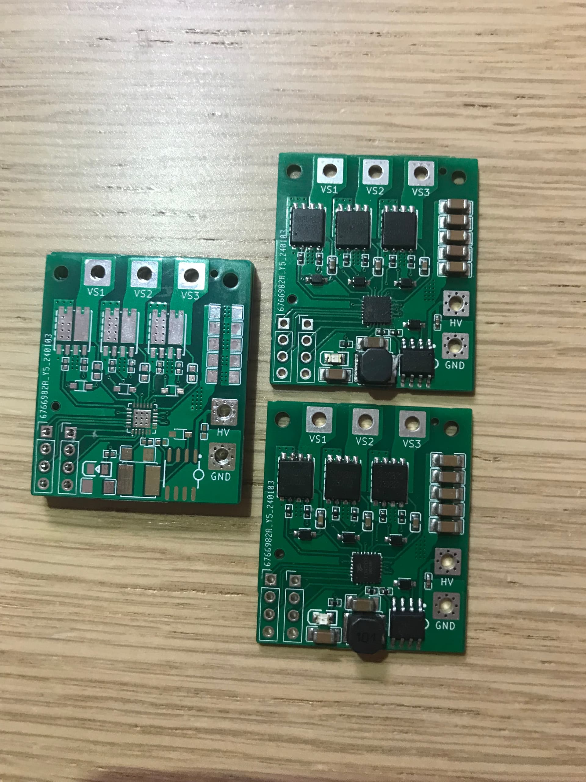
It doesn’t have to be a short causing the problem. If you checked carefully and could not find any bad connections, then I would say the next thing to check is the component orientation. If any of your diodes are facing the wrong way, the FETs or driver are mounted correctly, etc… I can see from the photo that the buck matches the dot on the PCB, but for the other components I can’t see.
And if everything is correct on the PCB, the next step is to re-check the footprints. If the footprint used in the layout doesn’t match the actual component, then it might look correct, but actually the signals are going to the wrong pins…
FETs, driver and diodes are the same ones as used in Valentine’s original design?
What do you actually have the voltage set to on your power supply? Or what are the characteristics of your power supply? If you are using something in constant-current mode then it would make sense to see low voltages here. It should be set in constant voltage mode, with a current limit, maybe 9-12V to make sure the driver turns on. I would do all this with the motor disconnected.
Buck converters can be VERY picky but if you just copied the design/parts from Valentine’s board then it should work fine.
can you look at it with a thermal camera or just poke around and see what’s getting hot? Also, of course try disconnecting everything from the board and see what’s up. I like the “pluggable screw terminal connectors” so I can plug things in and unplug them without messing up the wiring unduly.
As Runger said if you don’t mind sacrificing a board, I would just give it the proper levels. It could be a thing where the board draws a bit of current for a short time, and the power supply craps out the the system can’t function properly and draws too much current. But disconnect everything first.
If you power a board that has nothing connected to it and it still explodes well it’s pretty much never going to live anyway so it’s no loss.
Yes and no - I agree that having problems lowers the bar to sacrifice one, but perhaps once the issue is found its a simple fix… then it could be shame if you blew them all up.
well I was only suggesting blowing one up lol :). But if it’s any comfort I have a similar problem with the lepton, I can’t use them but keep hoping I’ll figure it out some day and have bunch of boards. Well, if you blow one up, you can look at it and see what part overheated, at least.