For a dev platform I wonder if building something around the MicroMod pluggable MCU might be interesting? You could then swap between a RP2040, STM32F405 or Teensy depending on your budget and preferences.
Someone might even put some additional STM MCU into that footprint? Perhaps given the new Arduino Giga the STM32H7 as the high-end option.
That’s a neat idea but for motor control not practical because the pins will be different, so you still need different boards. I recently developed a board like that and then you need to design different pluggable boards to match the pins, that’s why I made the G431 blue-pill pinout replica, that’s the closest I ever got to that idea. I mean, you could solder jumpers and stuff but then it’s no plug/play anymore.
For example, I want to swap my G431 with NXP (Teensy). How would that work? I will have to design pluggable boards to match my exact driver board pinout, so that’s same custom work as just designing an NXM driver board variant.
If you have a different understanding, let me know, I’m very interested in modular design. I’m not arguing, I’m not clear on the advantage here.
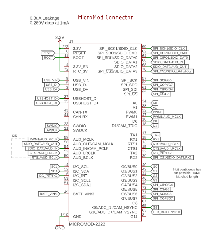
I don’t know if they are similar enough to do something with? You have I2C/SPI on each board, plus The A0>D1 section is always there, and GO > G7 seem to always be available. Micromod pin spec
I’m currently messing about with a robot using these MCU, once that’s at V1 the designer has expressed some interest in developing some custom MicroMod chips around STM. The STM32F103C8T6 (Bluepill) might be a good one to start with. Maybe in the slightly expanded 2242 footprint. (whilst retaining carrier board compatibility for the existing 2230.)
I’d be interested in doing an upgraded SimpleFOC driver/power board for the robot once the brushed version is tested and somewhat functional.
Although the micromod spec gives us a list of what each pin must be minimally capable of this (if I read the spec correctly) only guarantees 2 ADC capable pins and 2 PWM capable pins. Most boards will give you more than these of course, but which general pins will be able to do more? Do we just accept that some boards are incompatible if we select G0 through G3 as extra PWM pins and a new board adds the extra ADC capable pins first and starts its PWM capable pins later? Other problems could appear such as, do all the PWM pins we select fall under the same timer on the teensy board?
As I understand it, and I don’t pretend to be an expert here;
General purpose pins. Any unused processor pins should be assigned to Gx with ADC + PWM capable pins given priority (0, 1, 2, etc) ref
So you can assume PWM on Gx 0,1,2 if you don’t get PWM there then either the chip can’t support more than two, or the board designer has not adhered to the spec.
This is the biggest issue and where I see STM being a clear winner as far as generic pluggable MCU board is concerned. I can definitely see this working across the STM family, where you could choose lowest end G031 Chinese clone for a dollar or genuine dual core H7 for $100, and get the same pinout. Crossing MCU boundaries, I see the micro-mod geared mostly towards generic I/O and communications, not such narrow use case as motor control.
Pluggable MCU is definitely a great idea but needs to be standardized with the driver board. In a way, you create a custom micro-mod using the form factor but different pinouts, and stay inside the STM family, and pair with the driver.
Funny thing, I am currently working on a high power modular generic driver, which does something similar. May be in a few months I could show some progress. I believe a month ago I posted a small video somewhere on this board.
The other thing I notice, this works only with high value / high power boards, where modularity pays off. For low cost boards modular MCU is a huge cost item and will increase the overall complexity and end user price of the package.
Would it be possible to stay within the Sparkfun pinout, but to further define the rules/spec around allocating any additional pins? Then do a bunch of designs based on STMxx
You mean, allocate the same pins and then add extra pins for other stuff, or find out which pins are used for what and search the correct pinout configuration without adding extra pins?
I am looking at the pinouts and already see some problems
If you allocate more pins this will extend the board and you will not be able to plug it into the existing connector which looks like a standard M2 connector for a mezzanine board. Mechanically won’t work unless you solder a different board connector.
Or you had something else in mind?
The only way I see it, keep the idea of using this connector, but re-assign the pins and re-route different pins but then keep the core voltage and ground pins the same to power the board.
I think we’re talking at cross-purposes. I’m talking about extending and clarifying the existing Micromod ‘standard’ to make it more useful. Defining what signals should appear on which pin of the M.2.
If you are going to do your own boards anyway I think determining your own connector and pinout choice would be better. For use in FOC for example we might want to use something other than m.2 connectors as they keep the daughter board very close to the mainboard while a bit of distance would be good for thermal management.
That would definitely work, and I’m interested. Problem is I’m going on an extended business trip for a month to a remote place without internet and stuff and be back in April, then it takes a few weeks to try it out, we are looking may-june timeframe.
They pulled those high to 3V by hardwiring them, essentially killing the pins. No idea why. Also B1 is some interrupt. These pins are tied to Timer 1 on STM required for motor control. It may be possible to find alternative pins but that would probably kill the use of other pins and this will twist you into a pretzel finding what pin is doing what, and end up writing your own Arduino board variant, and this is really hard for novice users, and you can see some people on this board are having a hard time trying to program the Lepton board where the pins are already exposed and I posted even some sample code and @runger did a variant, which is a cakewalk compared to something like that.
But you don’t have to care how Sparkfun have done their board, (left side) that’s up to you/others to redesign, if Sparkfun has done a sub-optimal board here then that doesn’t really matter?
We only need to care about the Micromod compatibility (right side) and optionally clarify/ extend it.