Hi everyone,
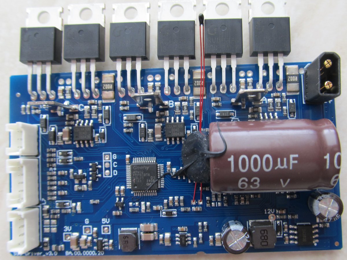
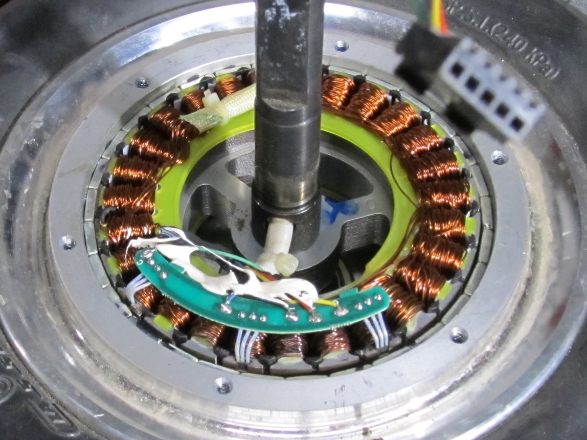
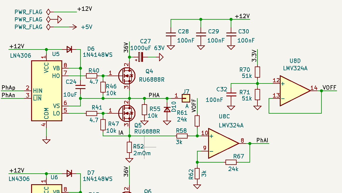
am trying to run hoverboard BLDC motor with cheap M365 motor controller from Ali. Schematic and STM32F103CB clone pinout are below.
Source code:
#include "SimpleFOC.h"
// POLES 15
// BLDC motor instance BLDCMotor(polepairs, (R), (KV))
//BLDCMotor motor = BLDCMotor(15, 16);
BLDCMotor motor = BLDCMotor(15);
BLDCDriver6PWM driver = BLDCDriver6PWM(PA8, PB13, PA9, PB14, PA10, PB15);
// hall inputs
// HALL_A PB4, HALL_B PB5, HALL_C PB0
HallSensor hSensor = HallSensor(PB4, PB5, PB0, 15);
void doA(){hSensor.handleA();}
void doB(){hSensor.handleB();}
void doC(){hSensor.handleC();}
// LowsideCurrentSense constructor
// - shunt_resistor - shunt resistor value
// - gain - current-sense op-amp gain
// lowside current sense instance LowsideCurrentSense(R, gain, phA, phB, (phC))
LowsideCurrentSense current_sense = LowsideCurrentSense(0.002, 8, PA3, PA4, PA5);
HardwareSerial Serial1(PB7, PB6); // cnrl
HardwareSerial Serial3(PB11, PB10); // batt
Commander command = Commander(Serial3);
void doTarget(char* cmd){command.motion(&motor, cmd);}
void setup()
{
AFIO->MAPR |= AFIO_MAPR_PD01_REMAP;
RCC->APB2ENR |= RCC_APB2ENR_IOPDEN;
GPIOD->CRL = 0x33;
GPIOD->IDR=0;
Serial3.begin(115200); // BSD
Serial1.begin(115200); // head
//analogReadResolution(12);
pinMode(PC14, INPUT);
pinMode(PC15, OUTPUT);
digitalWrite(PC15, 1);
hSensor.pullup = Pullup::USE_EXTERN;
hSensor.init();
hSensor.enableInterrupts(doA, doB, doC);
motor.linkSensor(&hSensor);
driver.voltage_power_supply = 32; // set power supply voltage
driver.init();
motor.linkDriver(&driver); // link driver to motor
motor.controller = MotionControlType::torque; // set motion control type to torque (default)
motor.torque_controller = TorqueControlType::foc_current; // set torque control type to FOC current
motor.foc_modulation = FOCModulationType::SpaceVectorPWM; // set FOC modulation type to space vector modulation
motor.voltage_limit = 28; // set motor voltage limit, this limits Vq
motor.init();
current_sense.linkDriver(&driver); // link driver to current sense
current_sense.init();
motor.linkCurrentSense(¤t_sense);
motor.initFOC();
command.add('M', doTarget, "motor"); // add command to commander
motor.useMonitoring(Serial3); // tell the motor to use the monitoring
motor.monitor_downsample = 0; // disable monitor at first - optional
_delay(1000);
}
void loop()
{
motor.loopFOC(); // main FOC algorithm function
motor.move(); // this function can be run at much lower frequency than loopFOC()
motor.monitor();
command.run(); // user communication
}
SimpleFOC studio doesn’t rum motor with START button.
Jogging control starts motor, but moving is very noisy.
What I am doing wrong?
Thanks in advance!
Are you sure this chip exactly works like a stm32f103 ?
motor.voltage_limit = 28;
is too high, check this.
For FOC to run well with hall sensors, you need to use the smoothing sensor, otherwise you have only one angle update every 4 degrees for a hoverboard motor.
You will have to set this when using it with hall sensors:
smooth.phase_correction = -_PI_6;
[EDIT] Looks like you jumped to FOC directly. You should follow the getting started on unknown hardware.
Thanks for the advice!
Somehow it started to work.
Although the Studio only works from time to time and I can’t figure out how to make it works every time.
BTW, under Linux it doesn’t like the line 37 in graphicWidget.py
self.plotWidget.showGrid(x=True, y=True, alpha=0.5)
it works after modification:
self.plotWidget.showGrid(x=True, y=True, alpha=1)
Another question. My circuit was not quite correct, the current amplifier has an offset. Is there a simple way to take the offset into account in the library?
// LowsideCurrentSense constructor
//  - shunt_resistor  - shunt resistor value, gain  - current-sense op-amp gain
LowsideCurrentSense current_sense  = LowsideCurrentSense(0.002, 8, PA3, PA4, PA5);
The phase current offsets are calibrated during the init of current sense.
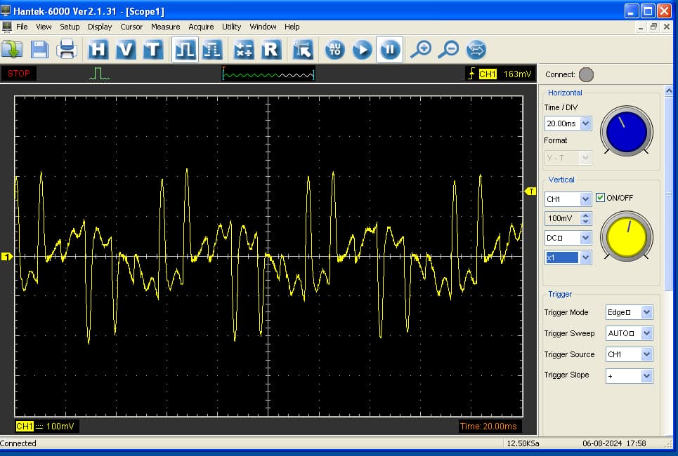
it is very strange, I have current like that:
Really current is about 10 times less.
What I am doing wrong again?
Are you mixing offset with gain?
Gain looks correct for me, sources are from example:
#include <Arduino.h>
#include "SimpleFOC.h"
// BLDCMotor(pole pair number, phase resistance (optional) );
BLDCMotor motor = BLDCMotor(15);
// BLDCDriver6PWM(pwmAh, pwmAl, pwmBh, pwmBl, pwmCh, pwmCl, (en optional))
BLDCDriver6PWM driver = BLDCDriver6PWM(PA8, PB13, PA9, PB14, PA10, PB15);
HallSensor hSensor = HallSensor(PB4, PB5, PB0, 15);
void doA(){hSensor.handleA();}
void doB(){hSensor.handleB();}
void doC(){hSensor.handleC();}
// LowsideCurrentSense constructor
// - shunt_resistor - shunt resistor value, gain - current-sense op-amp gain
LowsideCurrentSense current_sense = LowsideCurrentSense(0.002, 8, PA3, PA4, PA5);
HardwareSerial Serial3(PB11, PB10); // batt
Commander command = Commander(Serial3);
void doMotor(char* cmd) { command.motor(&motor, cmd); }
void setup()
{
Serial3.begin(115200); // BSD
hSensor.pullup = Pullup::USE_EXTERN;
hSensor.init();
hSensor.enableInterrupts(doA, doB, doC);
motor.linkSensor(&hSensor);
driver.voltage_power_supply = 36;
driver.voltage_limit = 42;
if(!driver.init())
{
Serial3.println("Driver init failed!");
return;
}
motor.linkDriver(&driver); // link the motor and the driver
current_sense.linkDriver(&driver); // link driver to cs
// current sense init hardware
if(!current_sense.init())
{
Serial.println("Current sense init failed!");
return;
}
motor.linkCurrentSense(¤t_sense); // link the current sense to the motor
// aligning voltage
motor.voltage_sensor_align = 5;
// set motion control loop to be used
motor.torque_controller = TorqueControlType::voltage;
motor.controller = MotionControlType::torque;
motor.useMonitoring(Serial3);
motor.monitor_downsample = 100; // set downsampling can be even more > 100
motor.monitor_variables = _MON_CURR_Q | _MON_CURR_D; // set monitoring of d and q currents
// initialize motor
if(!motor.init())
{
Serial.println("Motor init failed!");
return;
}
// align sensor and start FOC
if(!motor.initFOC())
{
Serial.println("FOC init failed!");
return;
}
// set the initial motor target
motor.target = 2; // Volts
// add target command M
command.add('M', doMotor, "Motor");
Serial3.println(F("Motor ready."));
Serial3.println(F("Set the target using serial terminal and command M:"));
_delay(1000);
}
void loop()
{
motor.loopFOC(); // main FOC algorithm function
motor.move(); // Motion control function
motor.monitor(); // display the currents
command.run(); // user communication
}
I am not sure if it’s the problem, but make sure you use floats properly:
I think this translates to a double for shunt and an int for gain:
LowsideCurrentSense(0.002, 8, PA3, PA4, PA5);
This will use floats:
LowsideCurrentSense(0.002f, 8.0f, PA3, PA4, PA5);
It was happening to someone recently that this initialization was used instead this one.
But this person had only 2 pins for current sense so 4 parameters, you might not have the same problem as you have 5 parameters.
Maybe it is my panic only - average current from power supply is about 70ma, but phase current looks like:
Picture is taken with my very slow current clamp Hantek CC65 (20kHz Bandwidth, 1mV/10mA).
motor.target = 0.5;
Max pulse is up to 2A.
But again don’t run foc without smoothing sensor.
Hi Vladimir,
Your code is working? Can you share it?
Thanks,
Robert
Yes, but it uses different way - EFeru’s FOC. Code is here: GitHub - trondin/ARM32_FOC_baremetal
Temperature measurement subroutine is not correct, but I do not use it in my code.
Thanks, i will try out. Just need to find my hardware