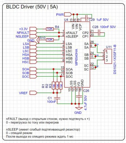
Hi. I want to read current from mp6540ha driver, but I don’t understand how to find the values of shunt_resistor and gain parameters for lowsideCurrentSense object, because the datasheet doesn’t specify the value of shunt resistor. I attach a piece of code that I use and the schematic where the driver and termination resistor are located. I also found the software for ROSMO Rosmo_ESC_firmware/src/main.cpp at master · runger1101001/Rosmo_ESC_firmware · GitHub, but when I also initialized the mp6540ha driver I got the error “CS: Err too low current, rising voltage!”
datasheet for mp6540ha: https://www.monolithicpower.com/en/documentview/productdocument/index/version/2/document_type/Datasheet/lang/en/sku/MP6540HA/document_id/6884/
> my kit: stm32g431cbu3, mp6540ha
*code "
#include <Arduino.h>
#include "math.h"
#include "SimpleFOC.h"
#include "SimpleFOCDrivers.h"
#include "encoders/mt6835/MagneticSensorMT6835.h"
#define SENSOR_nCS PA4
#define CURRENT_VpA (1000.0f/9200.0f)
HardwareSerial Serial1(PB7, PB6); // RX, TX
// BLDCMotor(int pp, (optional R, KV))
// - pp - pole pair number
// - R - phase resistance value - optional
// - KV - motor KV rating [rpm/V] - optional
BLDCMotor motor = BLDCMotor(7, 11.3, 196);
// BLDCDriver6PWM( int phA_h, int phA_l, int phB_h, int phB_l, int phC_h, int phC_l, int en)
BLDCDriver6PWM driver = BLDCDriver6PWM(PA8, PB13, PA9, PB14, PA10, PB15, PB12);
SPISettings myMT6835SPISettings(1000000, MT6835_BITORDER, SPI_MODE3);
MagneticSensorMT6835 sensor = MagneticSensorMT6835(SENSOR_nCS, myMT6835SPISettings);
// current sensor
// shunt resistor value
// gain value
// pins phase A,B
LowsideCurrentSense current_sense = LowsideCurrentSense(1.0f, 1.0f/CURRENT_VpA, PA0, PA1, PA2);
// instantiate the commander
Commander command = Commander(Serial1);
void doMotor(char* cmd) { command.motor(&motor, cmd); }
void setup() {
// init the serial port
Serial1.begin(9600);
// enable the debugging output
SimpleFOCDebug::enable(&Serial1);
// initialize encoder sensor hardware
sensor.init();
// link the motor to the sensor
motor.linkSensor(&sensor);
// pwm frequency to be used [Hz]
//driver.pwm_frequency = 20000;
// power supply voltage [V]
driver.voltage_power_supply = 9;
// Max DC voltage allowed - default voltage_power_supply
driver.voltage_limit = 9;
// daad_zone [0,1] - default 0.02 - 2%
driver.dead_zone = 0.05;
// init the driver
if(!driver.init()){
Serial1.println("Driver init failed!");
return;
}
// link the driver to the current sense
current_sense.linkDriver(&driver);
// link driver
motor.linkDriver(&driver);
// aligning voltage
motor.voltage_sensor_align = 3;
// choose FOC modulation
//motor.foc_modulation = FOCModulationType::SpaceVectorPWM;
// set torque mode
//motor.torque_controller = TorqueControlType::voltage;
// set motion control loop to be used
// motor.controller = MotionControlType::torque;
motor.controller = MotionControlType::angle;
// controller configuration based on the control type
// velocity PID controller parameters
// default P=0.5 I = 10 D =0
motor.PID_velocity.P = 0.02;
motor.PID_velocity.I = 0;
motor.PID_velocity.D = 0.00015;
// jerk control using voltage voltage ramp
// default value is 300 volts per sec ~ 0.3V per millisecond
motor.PID_velocity.output_ramp = 300;
// velocity low pass filtering
// default 5ms - try different values to see what is the best.
// the lower the less filtered
//motor.LPF_velocity.Tf = 0.1;
// maximal velocity of the position control
// default 20
//motor.velocity_limit = 15;
// default voltage_power_supply
motor.voltage_limit = 9;
// use monitoring with serial
// comment out if not needed
motor.useMonitoring(Serial1);
motor.monitor_downsample = 100; // set downsampling can be even more > 100
motor.monitor_variables = _MON_CURR_Q | _MON_CURR_D; // set monitoring of d and q currents
// initialize motor
if(!motor.init()){
Serial1.println("Motor init failed!");
return;
}
// init current sense
// current sense init
if(!current_sense.init()){
Serial1.println("Current sense init failed!");
return;
}
// link the current sense to the motor
motor.linkCurrentSense(¤t_sense);
// skip alignment
// current_sense.skip_align = true;
current_sense.driverAlign(motor.voltage_sensor_align);
// align sensor and start FOC
if(!motor.initFOC()){
Serial1.println("FOC init failed!");
return;
}
// add target command M
command.add('M', doMotor, "Motor");
Serial1.println(F("Motor ready."));
Serial1.println(F("Set the target using serial terminal and command M:"));
_delay(1000);
}
// timestamp for changing direction
long timestamp_us = _micros();
void loop() {
// Motion control function
static float target_angle = 36;
if(_micros() - timestamp_us > 1e6) {
timestamp_us = _micros();
// увеличиваем целевой угол на 5 градусов
target_angle += 36;
// если целевой угол больше 360 градусов, то сбрасываем его на 0
if (target_angle > 360) {
target_angle = 0;
}
}
// main FOC algorithm function
motor.loopFOC();
// Motion control function
motor.move(target_angle * (PI / 180));
// display the currents
motor.monitor();
// user communication
command.run();
}
"
mistake while compiling code "
TIM1-CH2N TIM2-CH4 TIM1-CH3N score: -6
TIM1-CH1 TIM1-CH1N TIM2-CH3 TIM1-CH2N TIM2-CH4 TIM15-CH1N score: -6
TIM1-CH1 TIM1-CH1N TIM2-CH3 TIM1-CH2N TIM2-CH4 TIM15-CH2 score: -6
TIM1-CH1 TIM1-CH1N TIM2-CH3 TIM15-CH1 TIM1-CH3 TIM1-CH3N score: -6
TIM1-CH1 TIM1-CH1N TIM2-CH3 TIM15-CH1 TIM1-CH3 TIM15-CH1N score: -6
TIM1-CH1 TIM1-CH1N TIM2-CH3 TIM15-CH1 TIM1-CH3 TIM15-CH2 score: -6
TIM1-CH1 TIM1-CH1N TIM2-CH3 TIM15-CH1 TIM2-CH4 TIM1-CH3N score: -6
TIM1-CH1 TIM1-CH1N TIM2-CH3 TIM15-CH1 TIM2-CH4 TIM15-CH1N score: -6
TIM1-CH1 TIM1-CH1N TIM2-CH3 TIM15-CH1 TIM2-CH4 TIM15-CH2 score: -6
STM32-DRV: best: TIM1-CH1 TIM1-CH1N TIM1-CH2 TIM1-CH2N TIM1-CH3 TIM1-CH3N score: 1
STM32-DRV: Syncronising timers! Timer no. 1
STM32-DRV: Restarting timer 1
MOT: Monitor enabled!
MOT: Init
MOT: Enable driver.
STM32-CS: Using ADC: 1
STM32-DRV: Stopping timer 1
STM32-DRV: Stopping timer 1
STM32-DRV: Stopping timer 1
STM32-DRV: Stopping timer 1
STM32-DRV: Stopping timer 1
STM32-DRV: Stopping timer 1
STM32-DRV: Syncronising timers! Timer no. 1
STM32-DRV: Restarting timer 1
CS: Err too low current, rise voltage!
MOT: Align sensor.
MOT: sensor_direction==CW
MOT: PP check: OK!
MOT: Zero elec. angle: 6.09
MOT: Align current sense.
CS: Err too low current, rise voltage!
MOT: Align error!
MOT: Init FOC failed.
FOC init failed!
"
sheme
