Looking for USB powered low power BLDC driver

I’d like to build a device similar to GitHub - scottbez1/smartknob: Haptic input knob with software-defined endstops and virtual detents. Instead of a custom PCB I’d like to use some cheap and readily available breakout boards that could ideally be powered directly from a PC with USB like in the smartknob (not in terms of a usb connector but in terms of voltage/current).

Size of electronics is not a limiting factor in my case. For a tech-demo a single unit would be sufficient but later on I would probably need > 5 drivers so price per unit should be as low as possible.

I’ve read the L298N consumes 2W without any load which doesn’t sound reasonable.

I hope for some advice. Thanks in advance.

Hi @nest90 , and welcome to SimpleFOC!

So I would be pleased to be corrected on this, but as far as I am aware there are no BLDC drivers which take their power from USB. There are lots which have USB ports for DFU firmware flashing or Serial comms, but none that I know of that route the USB power to the motor.

This is because doing so would be out of spec for old style USB, even small BLDCs would draw too much current when stalled. For newer USB specs, either the 2A charging, or USB-C with PD, it would be possible to power a BLDC motor.

I think to make a safe device, i.e. one that doesn’t cause damage to old style USB ports, you’d have to follow the USB-C PD spec, which typically involves a certain amount of chips and components (like a bunch of FETs to control the power path), and isn’t completely trivial to implement. There are plenty of reference designs associated with the different chips you can get.

You could look through the different newer boards out there from Sparkfun etc, perhaps there is one that can deliver 1 or 2A on its 5V rail - that would be enough for haptic, I believe. But most MCU boards have woefully underpowered LDOs for driving a motor, or have 5V directly connected to USB, which doesn’t seem like a good plan.

Another approach could be to just ignore all specs and potential problems, and power a board directly from USB – but using a good externally powered USB hub. I have one with a port tabled “Charging - 2A max” - maybe it will just work for the power levels you need… but I would not plug the resulting device directly to a computer or laptop, this way of doing it sounds more like a prototype phase approach :wink:

In terms of actual drivers, it is very difficult these days. Most products are out of stock. Check out some of @Valentine 's designs in this forum, perhaps when they are ready some of those would suit your project? Or maybe you can get your hands on a B-G431-ESC-1… It probably won’t meet your size requirements but a SimpleFOC shield and Nucleo board might be good enough for prototyping?
@runger is right I believe. 5V / 2A is the max you could draw from USB, and the old USB are 500mA.

@nest90 , welcome to the forum. I could check if something is available, however, 5V has three strikes against:

  1. Most drivers require high voltage to drive the booster circuit and shut down the silicon if they detect anything under 6V (under-voltage protection). Some of them will shut down under 8V.
  2. Most MOSFETs are very inefficient at 5V and will overheat easily (hence you will draw power even when idle).
  3. Current draw will be a problem for power supplies, and you may experience shoot-backs into your power supply. Example, if you power it via computer USB port and something happens to the motor, you will inject high voltage back into your motherboard, and some cheaper computers don’t have very good USB port protection, and you will kill your notebook/laptop.

I could check if this is even possible but don’t get your hopes high. It is possible to build a boost converter out of the 5V but those are also inefficient, and will complicate and make the board expensive. It’s a classic case of PCB design, pick a good and expensive or a bad and cheap one. Can’t have a good and cheap one.

Let me search into the database and see if anything pops out.

Cheers,
Valentine

Update. The EG2133 driver I used for the Lepton board lists minimum VCC at 4.5 V, which means hypothetically you may be able to drive the entire board with 5V.

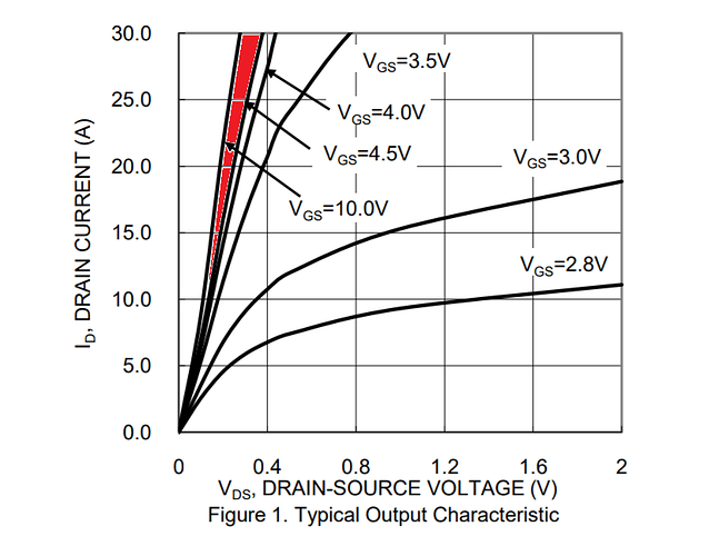
This is the thread for the board. It’s really cheap if you do not need current sense, and a bit more expensive if you do. The gate threshold voltage of the MOSFETs is 3V, and the drain-source voltage is such that at 5V gate and 5V drain you will be in the gray area where it will work but not quite the best, check out the figure at the end, red area.

I suggest you wait for the Lepton to get tested by me and you can order a batch if successful.

As far as the current drain at rest, that’s not a problem, the mosfets won’t consume much power when idle. How much power, since it’s 5V, I have no idea but I could test that use case when the board arrives.

As @runger mentioned, the silicon shortage is very dramatic currently and also combined with the COVID restrictions and the war against Ukraine, worldwide logistics are stretched to a breaking point. I’ve been waiting for a simple delivery already 3 weeks. Used to take 3 days max, now is a crapshoot.

The Lepton board is using the G031 MCU which requires somewhat elevated skills to program. Caveat emptor.

What is your use case exactly, can you explain?

Cheers,
Valentine

I did not expect so many in-depth reply’s in just a few hours. Thank you so much for your help!

I’m more a less trying to duplicate the features of the linked haptic knob (GitHub - scottbez1/smartknob: Haptic input knob with software-defined endstops and virtual detents) as a custom PC input device with some added feedback. Just watch the demo video on the smartknob page to see what I mean.

It is actually using simplefoc for controlling the motors. Everything is USB powered. It uses TMC6300 motor drivers (2…11V, 1.4A). See the project page for documentation and CAD data. It uses a custom PCB which somewhat hard to handle for me considering TMC6300 part size and lack of experience.

Therefor I thought maybe there is an alternative that might not be as good but more usable for a “simple” DIY project.

Right. Interesting, nice weekend project.

Two things.

  1. The Lepton board is driver only. No Serial. By no Serial, I mean, you will need an external transceiver to communicate with the board, and also you will need an external USB plug.

  2. No USB plug. This means you will need an external device to power it and solder wires. Which is a problem because most external USB devices are not designed to carry high current and you will probably melt the solder.

For you to do something like that, you will need to add a serial transceiver and USB power plug, which means, you will need an external board to communicate with the Lepton board, and that board will supply the power and talk to both the driver and the computer. Example

SparkFun Qwiic Pro Micro - USB-C (ATmega32U4)

Your other option if you want this to be productized and not a weekend project, is to develop your own fully integrated PCB from scratch using the EG2133 driver and discrete mosfets and USB transceiver, etc, which may not be within your capacity.

Give the semiconductor shortage being as it is, it really is not a good time to be designing new hardware :frowning: :frowning: :frowning:

But I think you can build your device as a prototype, there is a lot of work on the software side that you can get done before finalising the hardware design…

For example one of these:

with a Nucleo MCU board like this:

will give you an Arduino-compatible motor driver solution to prototype with.

Same kind of thing could be available more cheaply on AliExpress, for example by getting a SimpleFOC Shield and a Arduino form-factor ESP32…

These boards won’t be the final size/shape you want, probably, but its a way to start prototyping while you wait for the right driver board to become available, or work on a design…

Hi @nest90! In case you hadn’t seen it, I just wanted to mention that Trinamic makes a breadboard-friendly breakout board for the TMC6300, the aptly-named TMC6300-BOB, which is what I used for prototyping the smartknob. Although now that I look again, it seems to be sold out on DigiKey and Mouser, so I guess that’s not actually helpful for you… :frowning:

Looks like you can backorder on Mouser if you’re willing to wait: https://www.mouser.com/ProductDetail/Trinamic/TMC6300-BOB?qs=TiOZkKH1s2TC7GLAoPdOmA%3D%3D

With the TMC6300-BOB being a manufacturer-produced dev kit, it’s somewhat overpriced for what it is, so I’m hoping that there will be some more hobbyist-friendly boards developed with the TMC6300 in the future by the likes of Sparkfun or Adafruit. It’s still a very new chip but it really hits a sweet spot for small 1S or 2S battery-powered (or USB-powered) low current BLDC applications that other integrated drivers don’t cover.

I’ve already looked for the TMC6300-BOB because I’ve already read about it when looking at your project. For me it is currently unavailable. It is also a bit expensive when you need not only a single board but 5 or more. I’m hoping for a cheap alternative board.

@nest90

Would you mind please defining the price point? $10, $20, $30?

Cheers,
Valentine

$10 would probably be OK considering I also need the motors and the rest of the project. If its a lot more expensive it would end up in a region where I could buy an of the shelf product with similar features.

Thank you. In my experience even the cheap driver boards from China on Aliexpress are quite more expensive than $10, especially the “Door-2-door” price including taxes, import duties and shipping. When you say “driver”, are you looking for an integrated driver board (MCU + driver + MOSFETs) or just the driver power stage (Driver + MOSFETs) and you will drive it with an external Arduino-compatible MCU?

Cheers,
Valentine

I don’t know if you’re still looking for something like this almost a year later, but I recently got into simpleFOC and have made this small board, which you can power (and program) via USB, as well as external JST XH connector if desired. I am using it with the small cheap (~$3) BLDC motors from Aliexpress and having good results so far. You can see my design here: GitHub - VIPQualityPost/easy-esc: simple, small ESC controller with FOC implementation from SimpleFOC on RP2040.
The design cost about $35 for 5 boards fully assembled, minus the cost of TMC6300 (not currently in JLC PCB part library) and two JST connectors (not necessary for operation). You do have to place TMC6300 manually but this is easy with hot air gun or just placing the PCB on a hot piece of metal to re-flow the board (no parts on backside so it lays flat, at least until JST connectors are placed).

There were some small mistakes because this was my first time working with the rp2040 but they are fixed now. I am working on adding some support for magnetic encoders but this increases the price significantly and I don’t see any good candidate for assembly in China so I might just skip adding that.

3 Likes

@VIPQualityPost

Welcome to the forum.

Thank you, this is educational.

Cheers,
Valentine

Hi! I saw your design on github (easy-esc-encoded-rp2040). What is the state of the project? I’m looking for exactly the same solution.
Thanks!

1 Like

Hi eduard,

Over the past few weeks I have kind of been thrashing at a design. easy-esc-encoded-rp2040 is still in works, but I prioritized doing an STM32 design for right now, because I wanted better ADC performance for in-line phase current sensing. I really prefer the rp2040 right now for ease of use and will come back to this design once I wrap up my current one.
my main goals for right now are:

  • design can be flashed over USB, with virtual com port
  • can be fully assembled by LCSC (trying to avoid using tmc6300 since that requires hand assembly, but I haven’t found a replacement for all-in-one IC like that yet, so for now I’m going with discrete mosfets
  • priced under $10 per board (also why for now, we stay with STM32, I am trying just to only use basic components)
  • SPI, ABZ magnetic encoder (originally I was just using SPI, but I want the hardware interrupts from ABZ mode, which is why for now I choose STM32 since hw interrupts on rp2040 are not supported yet)
  • maybe current sensing, it does not matter much for these small motors I think but I am still curious to play with it
  • needs to be able to power entirely off USB 2.0 spec (500mA)
  • accessible UART, SPI, I2C, SWD

I am curious about my STM32 design, I want to compare the power draw of the discrete output stage to the integrated TMC6300 one. I will post here again when I finish that and when I come back to the encoded rp2040 design.

1 Like

Can I ask your application? I am just curious. I am still kind of hunting for an application myself.

Thanks for your detailed explanation. Once you are ready with the design, I would like to buy some samples, and if are good, some more. I need a ready solution to drive and contol small (80-100g) medium (200g) and large (500g) BLDC motors with the same controller. If you prefer mosfets is a better solution for me, since they can be adapted to motors if the PCB design alows it.

Do you need one with rp2040 mcu? Or would an STM32 board be fine?
Are you looking for velocity control or position control (i.e. drone vs gimbal)? The design is not really focused on high-current motors, there are many other ESCs and drivers that can do this already. I think the ideal load for these boards is <1.5A, even with external power supply. I am still happy to ship you a handful if you want after I test them if they work.

Since the STM32 can be programmed as simple as arduino, I’m ok with better design, containing STM32. I just want position control only on all motors, so they are gimbal motors and the bigger one maybe hoverboard motor or I rewind it to met the controller. It would be great to test them. I think they can hadle my middle size motors with 1.5A, but it would be better to handle 3-5A. I use these motors/controllers to make haptic knobs and rotating platforms for small (under 2kg) payloads.