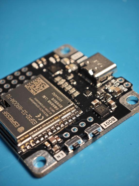
Hey! If you’re looking for a USB 3.0 driven low-power AIO?
I created a prototype based on the TMC6300 with MA710/MA730/MAQ430 sensors in the rear.
I’m now trying it with SmartKnob FW to see how well it works.
Although the construction is simple and affordable, I picked a very pricey sensor family.
The whole BOM, without assembly, is between 15 and 17 euros.
As long as you use a Type-C connection, it can manage the maximum rated current for the TMC while also powering the MCU and other peripherals.
A 5.1K resisor on the CC lines limits the board to 5V 3A. It will work with older USB devices, but you will be restricted to 500mA - NOT RECOMMENDED.
Specs:
ESP32-S3-1U N4R2
TMC6300 1.2A Max
MPS MagAlpha MA/MAQ series position sensors
Integrated TVS/ESD on USB datalines
ST1L05CPU33R - A nice compact but capable LDO
Type-C Conector capped at 5V 3A
Accessible UART, JTAG, I2C and other GPIOs
No Current Sensing
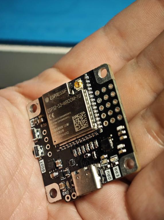
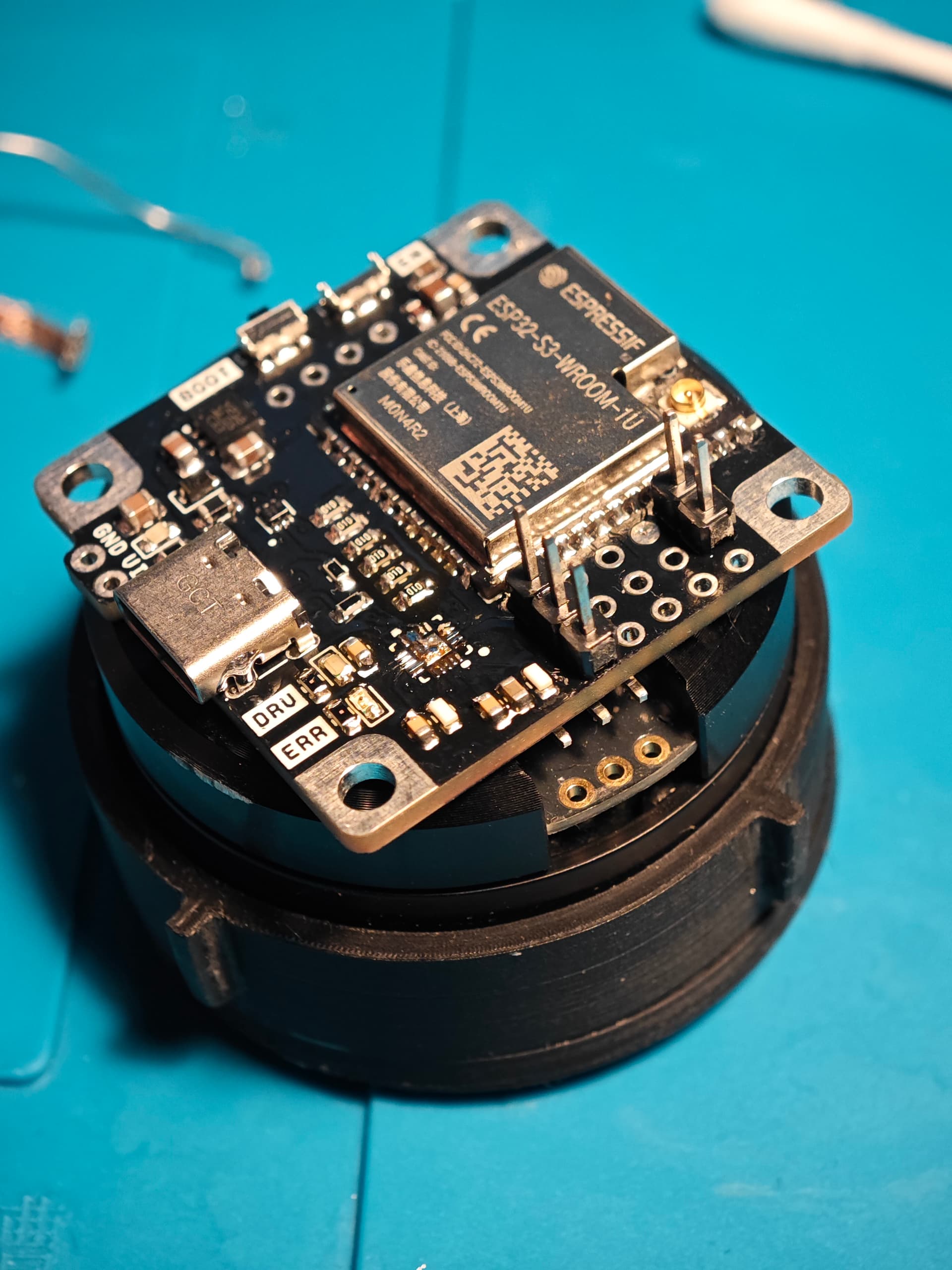
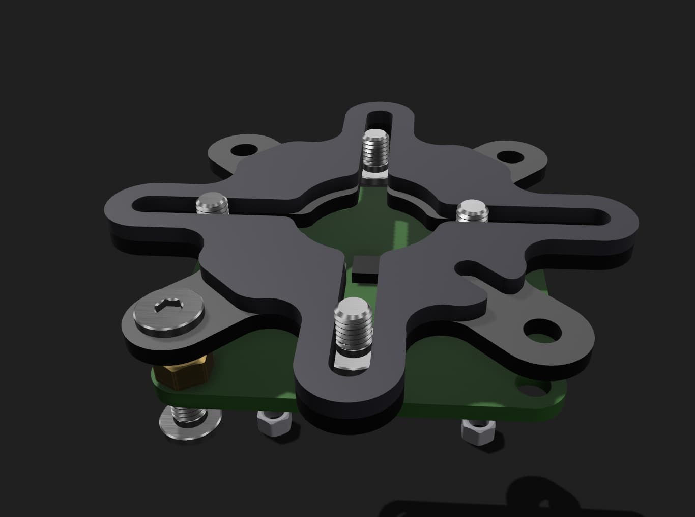
Footprint just 35x35mm! Its design to be mounted at the back of motor.
Supports wide range of low power gimbal or ptz motors.
Should work with many projects that use SimpleFOC.
I’m assembling first batch and need to test them and solve couple of issues of engineering nature.
Not sure when these would be available hehe depends on how i manage my free time
Any motor in particular? I would think stepper at first glance, but then you need one more half driver.
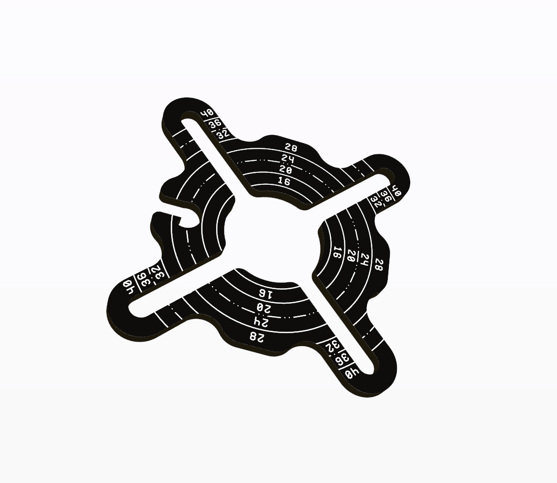
Is there a standard size for hole placement? On many of the small ones I get from aliexpress, the hole spacing seems random, almost.
Concept behind it was to keep it ultra small but big enough so you can attach few 2.54 headers.
Size of board is 35x35mm (+2mm for VIN GND notch).
It’s square form factor might be misleading that it fits Nema or other steppers but this is not correct.
I guess point I’m trying to make here is that the solution is of similar or exact form factor as some sensor boards. Yes maybe bigger than most of sensors hehe.
But you’d have low power AIO solution without cable mess, finding perfect sensor and driver, power issues or short supply wires. It’s USB powered but can be powered via VIN/GND headers (5-6V max as LDO cant handle more). It’s rated at 3A VIN max although i only had 2A Shottky available.
Also it has UART, I2C and Plenty of GPIO if you want to connect screen or other auxilary stuff.
It has 4MB Flash and 2MB PSRAM.
Idea behind it was for someone who want to jump into SimpleFOC projects but doesnt have Bench PSU, Solder iron, Hotair etc. can just hook up small gimbal or ptz motor and get to coding without hassle.
Yes i of course encourage getting to know theory and getting hands dirty, however a lot of people just want relatively cheap, comprehensive and hassle free solution.
That’s pretty brilliant solution for the motor mount spacing!
I also see the value in AIO board, which is why I have been working on mine (not done yet obviously)
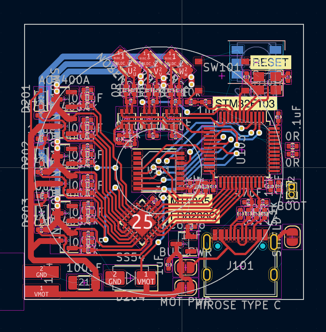
OK, I was not able to get SPI or I2C exposed externally, but this can be for the next revision. I will probably focus on CAN instead because I want all of these to hang out on one bus.
Additionally, I did not end up using SPI/SSI for the magnetic sensor MT6701. I tried to make some hacky configuration so that you can enable I2C bus to configure the chip, read registers if you like and maybe data, then disable the bus in order to use ABZ outputs. The chip is QFN16 but they only use 12 pins. I wish they would have put the serial ports on the unused pins so you can natively have both ABZ and SPI/SSI/I2C I am a big dummy. I didn’t think about using -A/-B/-Z in conjunction with the serial interface. To be fair they don’t really cover this in the datasheet (I assume the signal is just inverted?). Also, I don’t have pulldown for “mode” pin when serial is not enabled so I need some bodge wires. Current sensing is built into the PCB but I did not opt to place the current amplifier because I don’t really have a use for this with my current projects, I think. The current sense resistors share a footprint with solder jumper underneath so if you don’t want current sense, you can just solder jumper this and skip populating 1206 sense resistor + LT199G1 amplifier, it saves a couple of bucks. I should have got it placed anyway but I can’t cancel the order now. I don’t think anyone has used this chip yet for current sensing and it is a nice cheap bidirectional current shunt amp.
The motor voltage can be up to 12V but to stick with only LCSC basic components, the large 100uF buffer capacitor are only spec to 6.3V, this should only be used on USB 5V or other low voltage supply. If you build the board yourself you can choose just use better capacitors but the cost will go up.
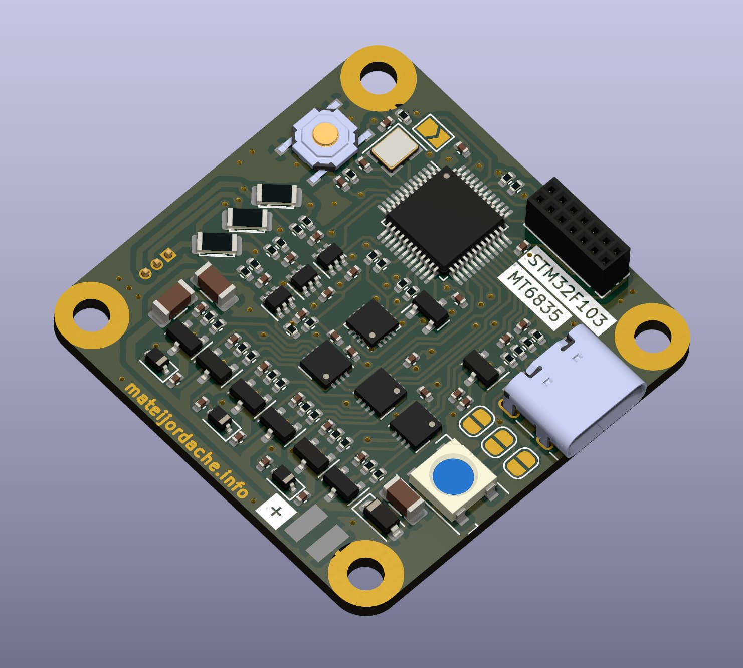
I did get a board that is 2 layer, top side only assembly, with all these features for < $10 USD per board (including both manufacturing and assembly), which I am really happy about. I am a bit sad about how the component layout is, I wish the third driver chip can be aligned more symmetrically, but it’s OK for this first rev, I think. My board only comes in at 38x38mm, so marginally larger than @Karl_Makes_Music. I just placed the order, so we will see how it comes out.
Hey! Simply great board! I really like layout and I wouldn’t be too bothered by asymmetric layout.
My first remark is that rule of thumb is caps being double the nominal voltage value, so that 100uF bulk cap at 6.3 should be at least 10 but better 16V.
yea, I know this should be, I might end up installing a higher rating later. I think 6.3V is already 25% headroom but maybe for inductive loads this is not enough. Mostly I was thinking that USB5V is already pretty clean and without any large motor current there shouldn’t be any large noise/ripple developed onto the main supply. We will see!
To be honest, I never include this in my hobby projects, but I recognize it should be there. I guess I can make room for the footprint anyway
Yes, I’m looking now. They have a bunch of ESD parts but I have yet to find one with termination components too. LCSC lookup is such garbage, I find myself just digging through pages with vague searches because if you are specific nothing will show up