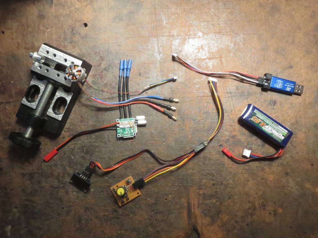
Dang, you’re right. I could have just wired up a manual reset button instead of buying the V3Minie. Oh well, I guess it’s nice to have a spare programmer.
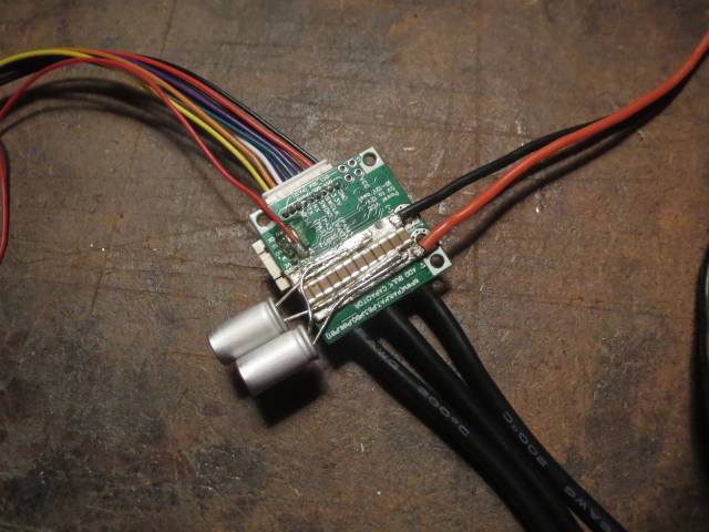
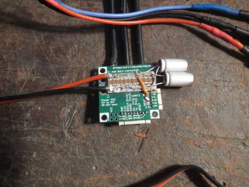
For my first attempt at diagnosis, I’ve got it set up to record the history of hall state changes using the onSectorChange callback. It uses a circular array of 512 values, recording the sector and time interval since last change. I removed the OLED from the mix and added an FTDI adapter so I can dump the history to serial monitor on the computer.
But when I went to test it, now the motor spins pretty smoothly even at 2V. It was the time spent writing to the OLED that was causing the trouble!
Basically the OLED update was creating a minimum time interval between stator field changes. No problem at low voltage when the natural time between hall state changes was longer than the OLED time, but at high voltage the rotor would quickly advance and settle in place where the stator field was pulling, and then sit and wait while the OLED updates, then loopFOC would run and change the stator field, and the rotor would quickly jump to the next position, and so on. Hence the fixed rotation speed but increasing vibration with voltage.
So it’s much better, but still not fully smooth, and one direction is better than the other. The history plot is fairly noisy. Running in forward direction at 2V, the time intervals range from 575us to 1753us. Sector 3 seems to have the shortest interval, being at most 991us. Sector 2 seems to be the longest, with no entries below 1290us. The rest are mostly around 1000us, but still a lot of variation. Holding the motor in my fingers (not touching the rotor), the motion feels mostly smooth but with occasional skips.
Running in reverse direction, times vary from 707us to 3183us. The shortest time is from sector 1, but it also has entries as high as 1885us. The longest entry is from sector 0, but it has entries as low as 2136us. Holding in my fingers, the motion feels rough.
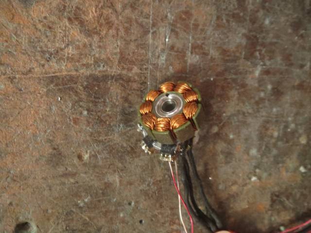
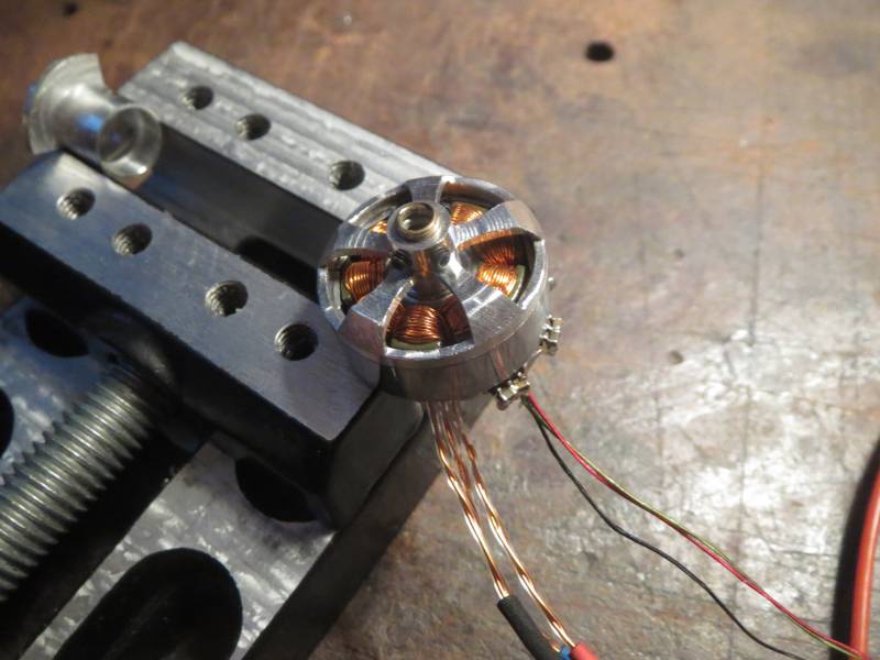
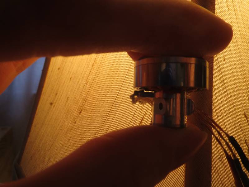
I’m pretty sure those outlying values are from the same two sensor changes, just showing as different sectors due to commutation direction. The placement of the sensors is about as perfect as it’s physically possible to get, but upon close examination it looks like one of them tilted by about 5 degrees when I was gluing them in place, so that’s probably what’s giving more time to one sector and less time to its neighbor. I’ll see if I can pop it out, scrape the glue off, and get it seated properly.
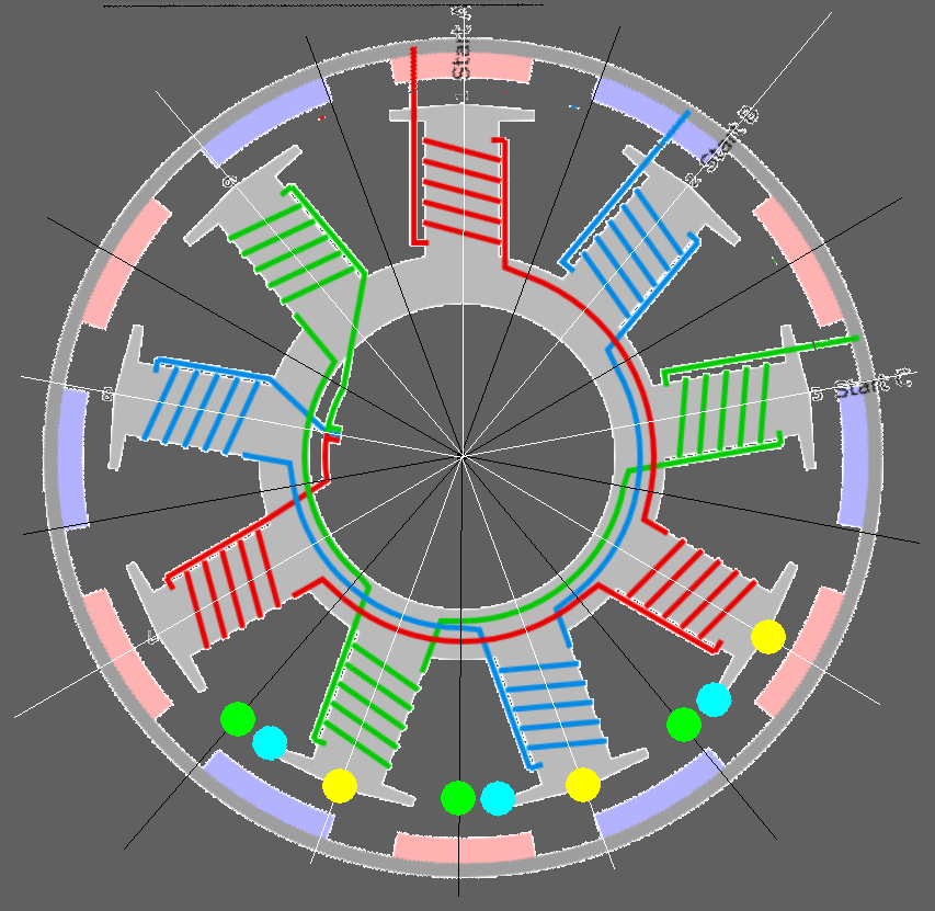
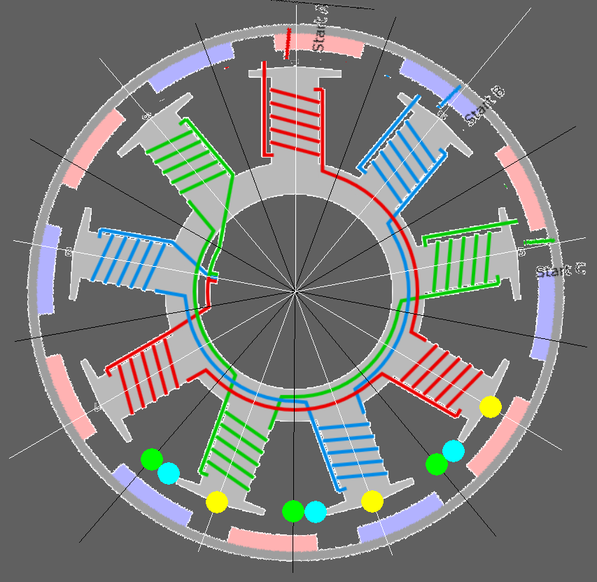
I’ve also made what I think is a more accurate sensor timing diagram. Energizing the red and blue coils should pull the rotor to this sort of position where two magnets are attracted to the two energized arms, and the idle green arms are pointed at gaps between magnets. This has the rotor turned 5 degrees from how I had it before, so now one cyan dot is centered on a magnet. That makes sense, because now that sensor won’t change state anytime soon, and the other two won’t change state either until the rotor has moved 10 degrees one way or the other.