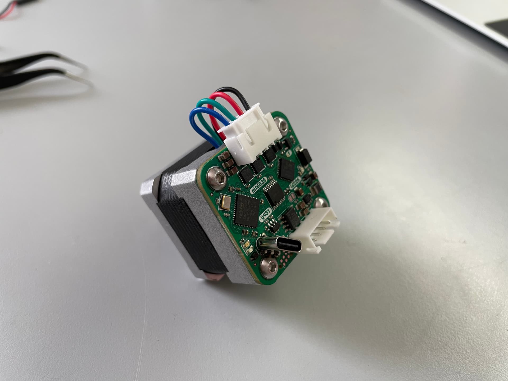
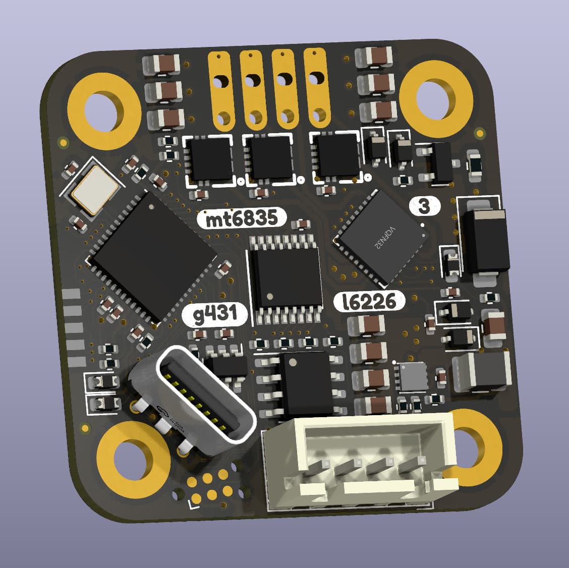
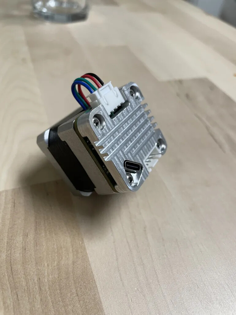
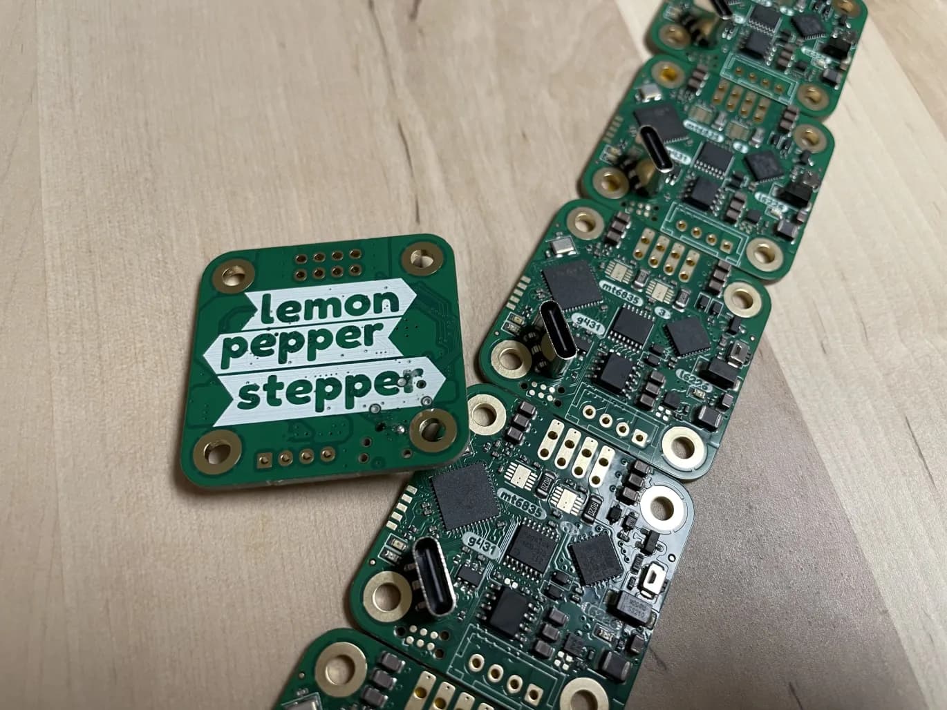
The Lemon Pepper board is a G431 based stepper and BLDC motor driver, with input voltage up to 48V at 1.5A, three inline current sense amplifiers, and 60V overvoltage protection. It uses the high resolution MT6835 in both SPI and ABZ modes, intended to be (configured and then) used with the low overhead STM32HWEncoder sensor class. The input connector can support step-dir (as a drop-in replacement for “dumb” open loop steppers), I2C, CANbus, as well as USB. The form factor is designed to mount to the back of NEMA 14 motors, but boards with larger outlines have also been produced to work with NEMA17 motors. The board is also single sided so friendly for both JLC and home assembly on hotplate. If assembled at JLC, the boards come out total to about $18 each. The BOM and board design have both been optimized to minimize cost and component count.
I have found some things during bringup that I will change for the next revision but this board is working really great for me so far! I am able to easily hit 300 rad/s at under 100mA (no load) on one of my steppers I had lying around. Still working on getting current sense up and running.
Thanks! @JorgeMaker it’s the ST L6226Q driver.
I don’t have a higher level protocol now, it just has the hardware to support those interfaces. You can upload using PlatformIO over DFU or SWD (using tag-connect header). I guess you could also use Arduino IDE but I don’t really know how to set things like build flags using that.
I wrote some simpleFOC canbus protocol for my last boards but it’s not very fleshed out at all.
Yes, it can be used as any type of USB device, it’s defined by the firmware. I am just using USB CDC (i.e. as virtual com port for serial right now).
@o_lampe No, unfortunately there is barely enough room as is, but maybe I can squeeze one or two small pads on. I don’t think any connector can fit. It’s really tight on the board.
I have some diametric ring magnets, so I mounted it on the shaft, then put a strong glue in the center (so no glue between magnet and shaft, just the glue holds onto both surfaces separately). I centered it by hand, it’s off by a bit, maybe 0.1mm but it’s hard to notice and doesn’t seem to effect the sensor too much. I am hoping that the MT6835 calibration will improve the linearity even further.
Banging my head on the wall here..
The PWM frequency I measure is half of what it should be (16kHz instead of 32kHz).
I can’t find the root of this- I am using a custom clock config, but it looks fine in CubeMX (and the generated code matches what should be generated) and initializing doesn’t throw any errors from the HAL RCC configuration.
The really weird thing is that if I increase PLL R clock div, it doesn’t appear to effect the PWM frequency. Moving from /2 to /4 should half the system clock frequency (and therefore PWM as TIM2 is derived from APB1) but no difference on my scope. Another funny thing is that SystemCoreClock global variable setup by the RCC code shows 336MHz with this configuration, even though it should be half of that. Changing the clock div from /2 to /4 does impact this and it reads 168MHz, although again that is twice of what the real frequency should be. I checked this also on my older AIOLI-FOC boards and indeed those are also running the PWM at half specified frequency, even though I also have a custom clock config on those. I did confirm my crystal HSE is actually 12MHz as well. @dekutree64@Valentine any ideas? I know you two did a lot of tinkering with clock code…
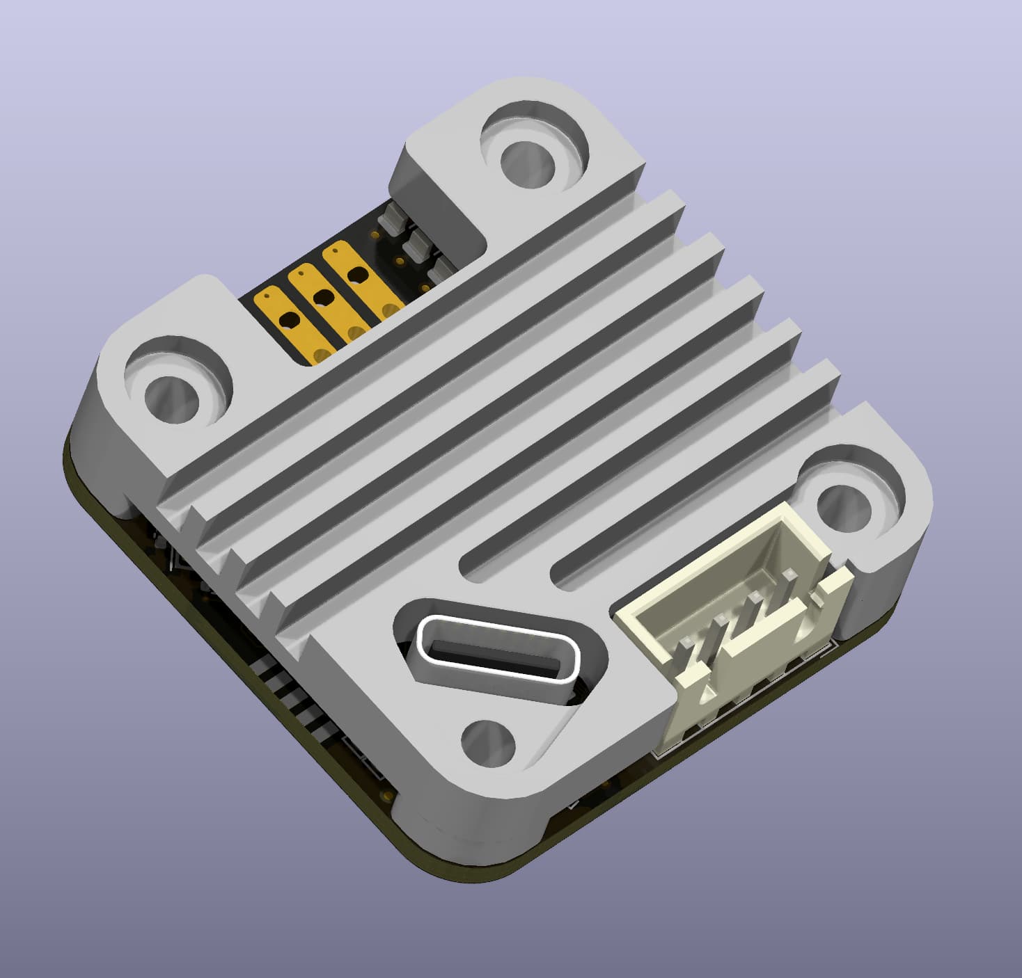
On a more positive note, someone recommended a neat idea of making a heat sink for the board as it’s getting quite warm at >1.2A. I tossed together a little design and got a quote from JLC. For 35x35x7mm part, the CNC machining service they offer quoted $10/pc for a qty of 10 parts, which isn’t too bad, although I was hoping it would come in a little cheaper.
Just figured this out- the print is wrong if you don’t define HSE_VALUE 12000000U, which makes sense as the default value is 24MHz, double what I was using… but the actual frequency still seems off, even though the PLL should operate the same regardless of input frequency.
Not sure about the clock, but for the heatsink you might try a quote for 3D printed aluminum too. It’s surprisingly cheap for small things.
Or for CNC, what are the tightest corner radii, like around the 4 pin connector? Standard length end mills are 4x as long as they are wide, so for 7mm thickness you should plan for a 2mm diameter mill (1mm radius).
Yes, actually someone in the discord also ordered this board with NEMA 17 outline/mounting holes. It could be done for NEMA23 but to be honest, I think you can make a design which is cheaper and with higher current capacity if you have the space. I was really constrained with the 14 design.
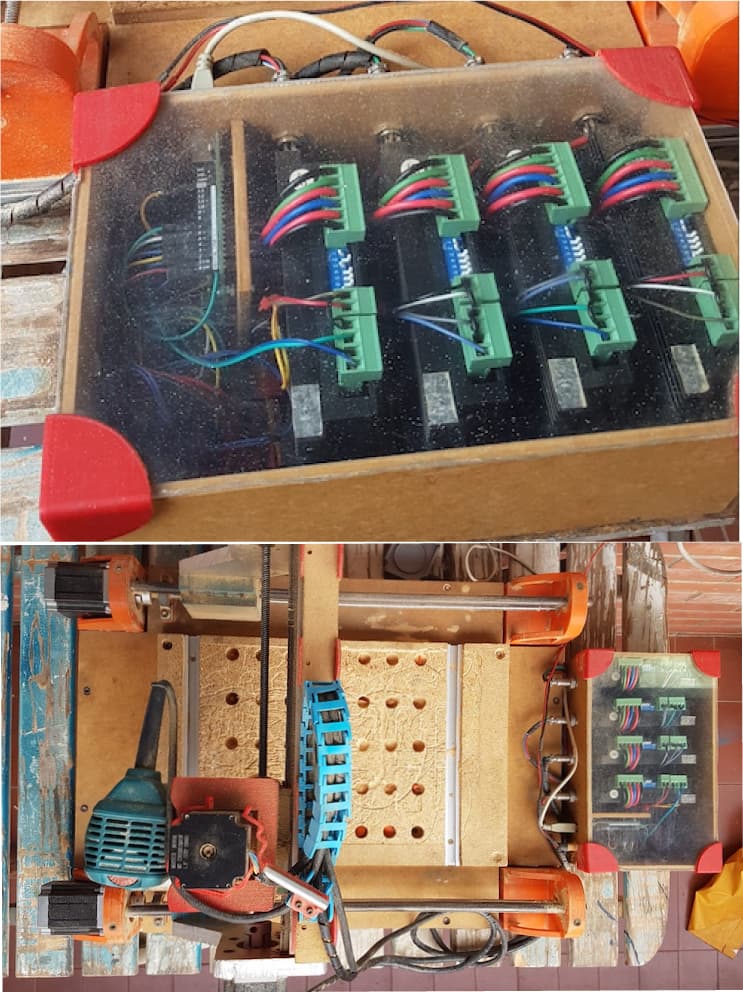
Maybe next year I’ll try using your design to upgrade my CNC router to replace the driver box with boards based on your Lemon Pepper design … running SimpleFOC
Hopefully!! I’m really trying to get my 3D printers running using simpleFOC
There has also been some effort by @Copper280z (who has some lemon-pepper NEMA 17) for getting a Klipper node working and @Juan-Antonio_Soren_E for a motion planner, so it really feels like we are getting close !!
Fixed the issue with the clock speeds!
Actually, it seems like the HardwareTimer code uses the SystemCoreClock as the basis for calculating the prescaler to the timer for PWM. So if that is wrong, then the derived PWM frequency is wrong. Yesterday I posted about #define HSE_VALUE 12000000U but actually, this doens’t go in main, it needs to go as a compiler flag !! So in platformio.ini, the “real” HSE clock speed should be passed in:
build_flags =
        -D HSE_VALUE=12000000U
@Valentine , @dekutree64 you may want to try and add this for your boards, as while the main clock speed will still be running at your frequency derived from the PLLs (so loop freq should be unaffected) , the actual peripheral frequency for PWM and others used may be off by what the code “thinks” your HSE actually is.
Have not had a lot of time for hobby lately… but here are some small updates:
New rev arrived, bringup looks good, the USB port seems problematic for assembly (minor issues) so I might try to change the part.
Heatsinks arrive and fit great.. I am really surprised and happy with the cost and quality of the JLC machining service.
edit: looks like earlier I posted a dead link to a branch which I merged… here is the link to the main project: GitHub - VIPQualityPost/lemon-pepper-stepper: simplefoc all-in-one 50W hybrid stepper + bldc driver
This is really interesting, I wonder if I could omit the angle sensor and use this as a sensorless motor driver board. I would have to figure out the flux observer posted elsewhere and a few other things but if I could get current sensing working on all 3 or even 2 phases that should be doable. This is all the current I would need.
I would like to get a single even more general purpose board designed, however. so there are 4 boards I will have to consider now, the leptonG4, QUADVRANS, b-g431-esc1 and this one, to weave together and steal the best bits to produce a single very general purpose board. I understand part of the strength of this one is that it has the sensor on it etc. though which is cool.
I designed it myself but I got made in China at JLCPCB, they have a CNC service. I got 10pcs made, so they do low qty runs for pretty cheap (~$8 ea).
Actually, @Copper280z has been working on getting sensorless working with simpleFOC (using this specific board), he made pretty good progress although things are rough around the edges still. In general for what you post about on this forum I think it might be too low power for you.
Actually, I thought this was going to be really cool, but if you want to use inline current sensing, it ends up being a headache. You basically need to get hall sensors for any common mode voltage >26V (hard to find parts otherwise), and the hall current sensors pick up magnetic field from both the motor and the encoder magnet. I ended up changing the parts here (ACS711KEXT) to one of the only current sense amps that is not hall-based with common mode voltage up to 60V (your only choice in a package this small is the MAX49925).
Really nice board here. Really nice. We were looking into something very similar for an open source 6-dof robotic arm, specifically the Arctos 6-DOF robotic arm. Our main aim is to also connect an external encoder, such as the AS 5600, to achieve more precise position measurements for the axes after the belts and gearboxes. The problem is that we would need to add secondary header for an I2C bus on the Lemon Pepper board, as in the current version can/i2c are shared to the same header, and we need them both at the same time.
Do you believe this is something of interest to you? Maybe we could beta test the motor board and develop together the can protocol The discord is Arctos Robotics in case you want to take a look on the current discussions.