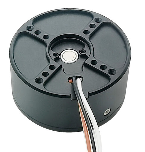
Hi! I have a bunch of GIM4305 motors that I had forgotten about. I came across them again and wanted to get them spinning, but noticed that they all already have a diametric magnet encased in the shaft. These magnets are too far from the Hall effect sensor when I mount my motor controller.
I tried removing the magnets but they’re really stuck in there.
Could I potentially mount another magnet on top of it to reduce clearance? I’m short on ideas for this predicament and I hope to not have to buy all new motors.
Can’t you mount the encoder IC closer to the magnet? How close can you get?
I don’t think mounting another magnet on top is a great idea. The magnets natural alignment would be that the opposite poles align to cover each other. But in this configuration the magnetic fields would be in opposite directions, not what the sensor likes. And getting them to align so their magnetic fields point the same way will be difficult to do accurately.
My guess is it would probably work in both configurations, but just less well than with a single magnet of the correct type.
In the end, best just try it out. Make sure you fix the second magnet in place though, just the magnetic force of the first magnet won’t be enough to prevent it moving a bit as the motor accelerates.
Yeah… AS5047P is essentially the same in terms of SPI interface but also has a ABZ encoder interface compared to the AS5048A. Same company makes them.
I would also have less expensive SC60228, with SPI but only 12 bit. I also just made up some 16bit KTH7812 sensors if you’re interested in trying those.
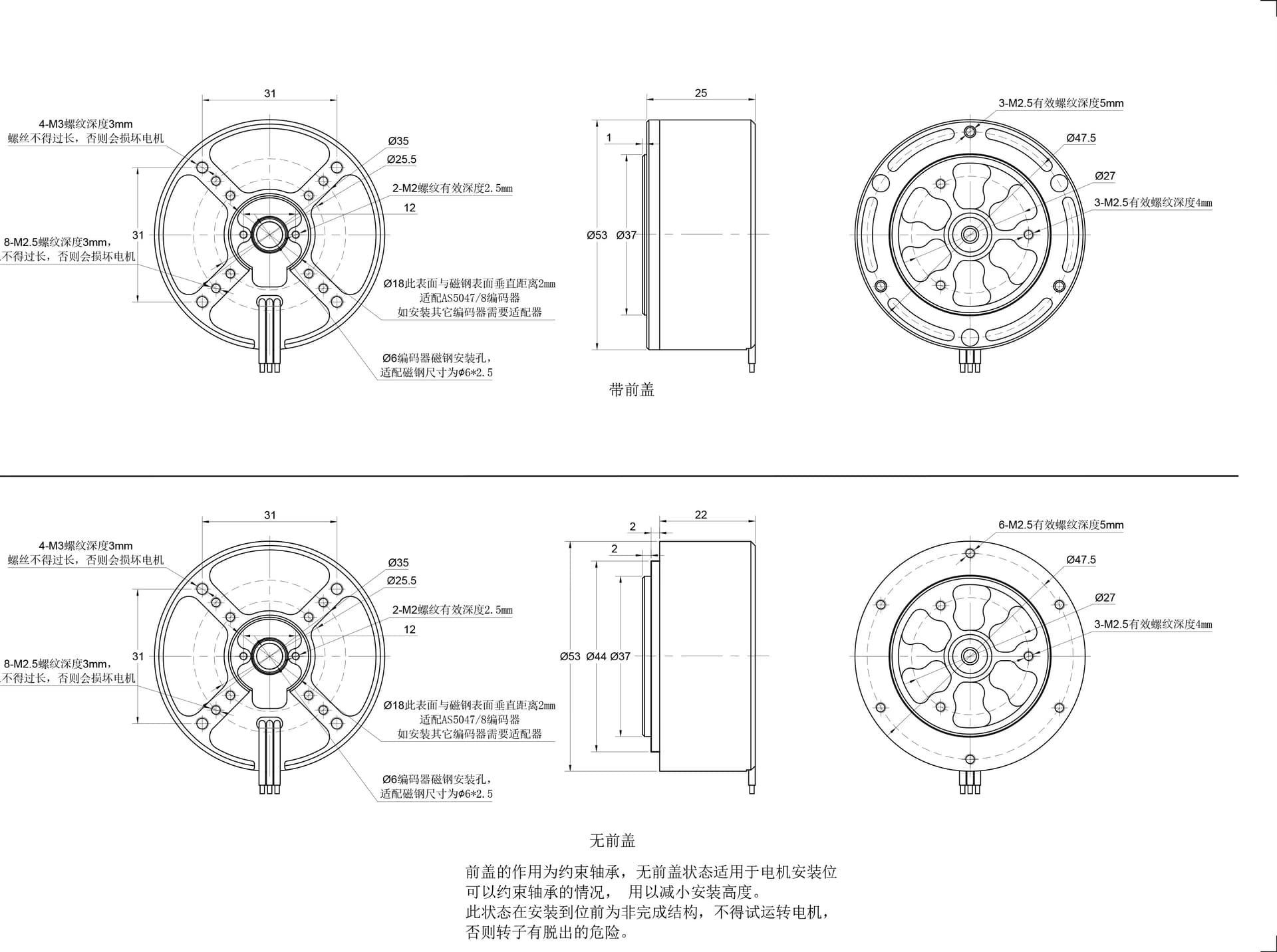
The PCB resting on the two screw holes is the lowest you could bring it down. The sensor chip has a height of 1mm. From the looks of things that would work out quite well…
Can they work with TinyMovr? On its website it says for v5.3 it has external SPI sensor support, so I would say yes in terms of the hardware, but I don’t know whether it’s firmware supports these sensors, and you’d have to make yourself a cable to go from the GH to the SH plugs.
No, don’t stack the magnets, your encoder won’t like it. I had some bad experiences with stacking magnets on top of one another with the exact goal as yours to reduce clearance, and the reading was very glitchy. Also the calibration procedure by SimpleFOC at init gave different results almost every time. So yeah, don’t do that.