I am not sure if it is better to make simpleFOC support DRV8301 x6 pwm mode?
Hi @zhangzq71!
You have a very good question.
The biggest reason why I did not implement the 6PWM mode is because it would make the code very complicated and hardware specific. Also, it would not be possible to implement it on Arduino UNO devices without using bit banging methods.
But it is not ruled out as a feature for the future releases.
Now in terms of the question, would it be better than 3pwm mode.
What you would do with 6pwm control would be that you would calculate 3pwn signals and then invert them in software/hardware of your microcontroller with some dead time. The 3PWM mode does the inversion for you inside the DRV chip and you can configure the dead time using either SPI (DRV8301) or voltage divider(DRV8302).
Therefore the choice is basically, where will you do the inversion. At the moment we do it in the bldc driver chip (L6234, DRV8302, DRV8302, DRV8305, …), but with 6PWM mode we would do it in the software in the MCU.
The benefit of this implementation is that you could potentially control the MOSFETs directly, without having to buy additional chip such as DRV8301. And it would open this library ro many many custom applications. Therefore I have included this on my roadmap long time ago 
But to have the complete benefit of using full 6PWM control we would need to have a current control loop and that is one of my most important future steps.
Let me know what do you think, did you have in mind some specific application or an issue?
Hi, @Antun_Skuric,
I am very glad to know you have the plan to implement the 6PWM mode. How about using the STM32 MCU that has the complementary PWM output cability, there are many motor control projects based on STM32 so I think that will be a better choice.
ZhangZQ
Hi @Antun_Skuric,
I am trying to figure out the difference in motor control performance (mostly interested in position mode accuracy) between using 3PWM and 6PWM. Reading your post here, it seems that the main difference between the two control modes would be less chips in the driver. Is that correct?
If not, could you let me know what are the advantages of using 6PWM control over 3PWM?
Thank you in advance. (I haven’t been able to find anything satisfactory on google.)
Best,
Nat
Hi @ngalin ,
Choosing 6PWM or 3PWM driving has no influence on the FOC-algorithm itself. The FOC algorithm and all the motor control code work only with at most 3 phase voltages.
The question of 3-PWM vs 6-PWM is relevant to the driver stage only. Different driver circuits require different control schemes.
All half-bridges have to be protected against “shoot-through” (short circuit due to both FETs being open) - this is what the dead-time is for, to ensure that one side of the half-bridge is fully off before the other FET switches on.
In 3-PWM control you must use a driver which handles dead-time for you. In 6-PWM control, you can control the dead-time directly by varying the duty-cycles of the centre-aligned PWM control signals. So in this case you can use drivers with no dead-time features, and independent control of the FETs.
So the different PWM modes mainly enable different driver circuit designs.
Hi @runger - thanks appreciate the explanation. That make sense.
So then one would choose 6-PWM control because they want to use a particular FET H-bridge (chosen say for higher current/lower latency/response times)?
Yes, absolutely.
For example, a half-bridge driver with built-in dead-time control is necessarily more complex, and therefore more expensive than a simple MOSFET driver without dead-time control.
So by using 6-PWM you can use the simpler, cheaper drivers.
Or for higher powered applications, you might not find a half-bridge driver capable of driving your MOSFETs… so you may prefer single channel FET drivers which can handle higher loads, and use 6-PWM to control them individually.
Things like this.
But generally speaking, if you have a driver/FET/motor combination that works well with 3-PWM control, and the cost of the design works for you, then this is preferable to 6-PWM control, since it will use less resources on your MCU.
1 Like
Hey guys,
You’ve already passed through the most relevant topics about 6pwm and 3pwm difference.
I’d just like to complete the discussion a bit.
In terms of FOC when using PWM modulation none the less if its sinusoidal or space vector there is no real difference in between the two.
The 6pwm is a bit more complicated to setup in software and has several more parameters like the dead time. But it essentially, with simplefoc, does not give you any other performance benefits.
So the choice is mostly related to the type of hardware you’re using: your driver architecture, your microcontroller capacity to driver 6pwm and the available pinout and similar.
For the FOC algorithm in it’s standard form no real difference.
However, having all 6 mosfet switches available has some benefits, you can disable certain phases by setting high and low side mosfets to the high impedance. This can be usefull when you’re implementing the BackEMF control of the motor, there you are obliged to disable one phase and measure the induced voltage on it, using the 3pwm you are not able to do that (except if yor driver has one enable pin per phase - but even then you need an additional pin to do it).
Another interest of having all 6 mosfets controllable is to avoid using PWM at all. You can bang-bang control your BLDC motor by choosing wisely which switches to open and when. The true Space vector algorithm is implemented not using the PWM but by controlling the switches directly, and the main benefit of the space vector modulation is that it provides you with a sequence of turning on and off the switches in a way that you never need to change the state of more than one switch (mosfet).
However these options are not implemented in the simplefoc for the moment, but might come at some point ![]()
I would be interested to at least support BackEMF control at least.
1 Like
came across this about while trying to understand the 3 pwm and 6 pwm modes and i have a doubt on the pins on drv8316
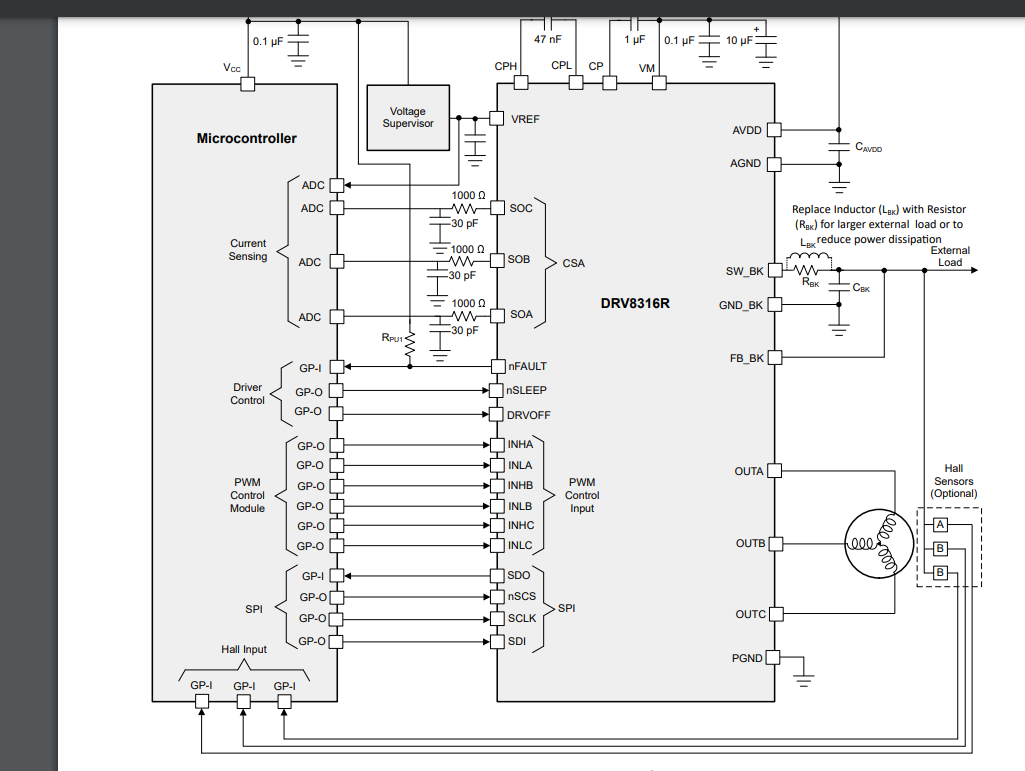
there is a 3 sets of INH and INL.
In 6 pwm mode all them will be used so what happens in the 3 pwm mode??
sorry if i understood it wrong can you please explain it so confusing !!
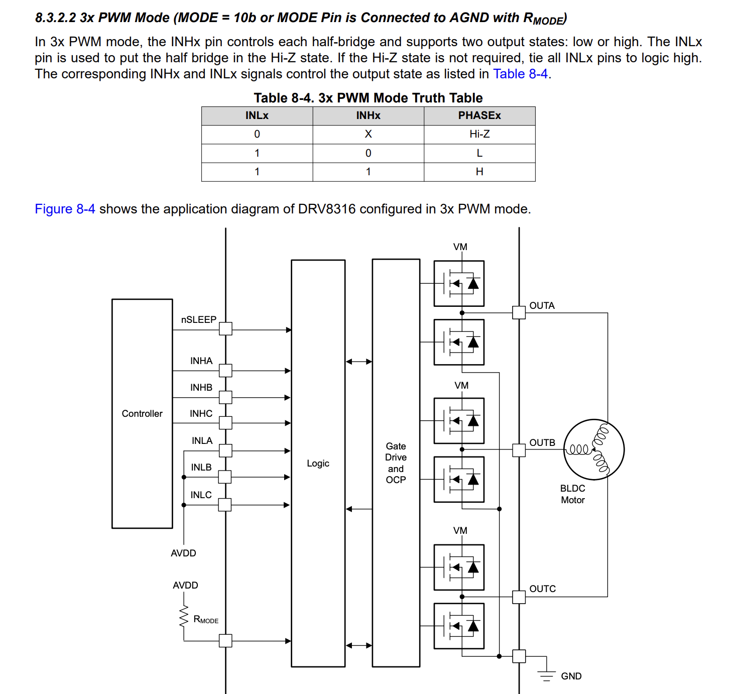
They describe how 3PWM is used in the datasheet. The “INLx” pins are tied high to use this mode. Or you can configure the MODE pins, and then use “INLx” as an enable signal for each channel.
okay thank you can i do position control with this using an arduino and AS5048A? and if i;m using arduino is there any default pins defined or should use random pwm pins
You are kind of hijacking a 4 year old thread… please make a new one if you have general questions about using the library.
You can’t pick random pins, you need to know which are PWM-capable from the Uno. I recommend reading docs, it is mentioned there many times: Writing the Code | Arduino-FOC