I’m experiencing significant current_q overshooting when the motor encounters obstacles.
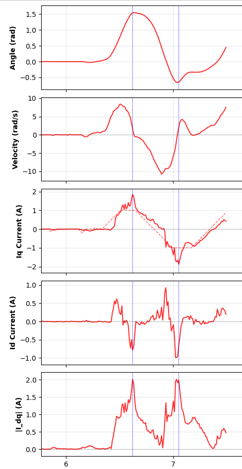
Expected Behavior: When setting target_current_q = 1.0f as shown in the diagram as red dotted line, the measured iq_value as shown in the diagram as red solid line should remain close to the target, even under load variations.
Actual Behavior: When the motor hits an obstacle, the measured iq_value spikes well beyond the target value (see attached diagram - red line shows measured current, dotted line shows target).
Recovery Time: It takes approximately 200ms for the current to recover from the spike and return back to the target region.
Questions
Why is the current controller allowing such significant overshoot beyond the target current_q value?
Is the 200ms recovery time normal, or does it indicate a tuning issue?
What parameters should I focus on tuning to minimize this overshoot when hitting obstacles?
Could the 1.6kHz loopFOC frequency be insufficient for my application?
Additional Context
The spiking only occurs when the motor encounters sudden mechanical resistance (obstacles). Any guidance on tuning the current control loop or adjusting relevant SimpleFOC parameters would be greatly appreciated!
What behavior do you get with the default current PID values (P=3, I=300, Tf=0.005)? I tried tuning it once, just out of curiosity, but the defaults seemed to be very good.
1.6KHz is very slow for the main loop, but I still wouldn’t expect more than a few ms to suppress the spike. Is there a reason you’re running it so slow, despite having plenty of processing power on the S3? 5-10KHz would probably be better.
Hi, deku. Thanks for the reply. I have tested with both the suggestions you have provided:
Right now the frequency of the motor.loopFOC() is around 5kHz as I have increased the clock speed of the AS5048B (I2C) to 1MHz.
Just the idea of doubting whether is the angle updating fast enough so that it won’t bottleneck the loop. The test I have done is just increasing the I2C clock speed and the time used to run the motor.loopFOC() has reduced, so I have decided to stick with just 1MHz of the I2C clock. And I am not sure is there any other way to increase the current loop frequency (motor.loopFOC()) more.
But still, the problem of the spiking Iq is not resolved.
I have tried with the current PI controller with values of Kp=3, Ki=300, and Tf=0.005, the PCB board restart immediately when the torque is exerted by the motor. The restart reason is as follow: BOD: Brownout detector was trig rst:0x1 (POWERON_RESET),boot:0x12 (SPI_FAST_FLASH_BOOT)
5kHz seems quite good with an I2C sensor… to further improve the loop times I think you would need to switch to an SPI based encoder…
The fact that you get brown-out with the default values tells me that, combined with the faster loop times these PID settings are “too aggressive” for your power supply - currents are rising too fast. You can try to mitigate this by:
adding some more bulk capacitance to support the sudden current demands
Setting the ramp value to a lower value to limit the rate of change of current in the PID
Tuning the PID with “less aggressive” values to make the change slower and not trigger the brown out
Also take a look at your LPF settings, if used, since a faster loop time may change the value you want to use there.
Of course, if you make the PID less responsive/ aggressive then it will also be slower to compensate your overshoot…
That would be PID_velocity.output_ramp, not the current PIDs, correct? You want the current PIDs to respond as fast as possible to prevent the motor from pulling excessive current when the speed (and thus back EMF) drops suddenly. Velocity output ramp prevents sudden changes in commanded current.
I would guess that the slow response to spikes is due to your low current P values, so we need to figure out why you’re getting brownout with higher values. I’d expect just the opposite, that faster response would reduce the peak current and prevent brownout.
Hi, all. There is something I need to clarify — about the test result as in my previous comment. Let me clarify the test result again and update the latest progress and results.
Increase the I2C clock speed will increase the frequency of the motor.loopFOC(). And now I always stick with the I2C clock speed of 1MHz as it still holds true.
The previous brownout is because the power is not connected properly. Now it can work as normal without any brownout issue.
The thing I have done today is trying to increase the frequency of the log and here I attach the plot again for a better description of the situation right now. The thing is the similar to the one I described at the top of the post, just that the resolution of the plot is higher.
For more context, in the plot of the current_q, the dotted line is the target_current_q and the solid line is the measured_current_q. Across all the plots, the blue vertical lines are the time when the motor hit the obstacles.
Hi, I have tried to play with the output_ramp value and I do not think so this is the parameter that I would like to tune. I have tested with value of 1000, 500, 200, 100, and 10. With output_ramp = 10.0, the response is very slow. In conclusion, the smaller the output_ramp, the slower the response of the motor.
Right now my current PID setting is Kp = 0.1 and Ki = 80.5. One interesting fact is that, I experimented only with Ki = 10.0, I would refer this as the “viscosity” is being introduced where the resistance is there and uniform when I move the motor shaft manually.