Then I don’t know.
A shift in the zero electrical angle would bias the d current but I don’t think it would look sinusoidal.
You need to investigate more.
Then I don’t know.
A shift in the zero electrical angle would bias the d current but I don’t think it would look sinusoidal.
You need to investigate more.
Is there a reason the I terms for Q and D are 0?
If I increase the I terms the motor starts oscillating also lowering the P term and add some I the system goes unstable. I think that is generated by the Id that is not dc.
hmmm I think your PIs are not being able to stop the oscillations. You can try lowering the P term and adding some I. I had some mechanical oscillations that went away with PI tuning, I have never seen no I term for current controlling.
You could check the d/q currents while in voltage mode.
So the PIs don’t interfere.
You will have to use something like that in the main loop:
DQCurrent_s dqcurrents = current_sense.getFOCCurrents(motor.electrical_angle);
Keep in mind d/q currents are not filtered here.
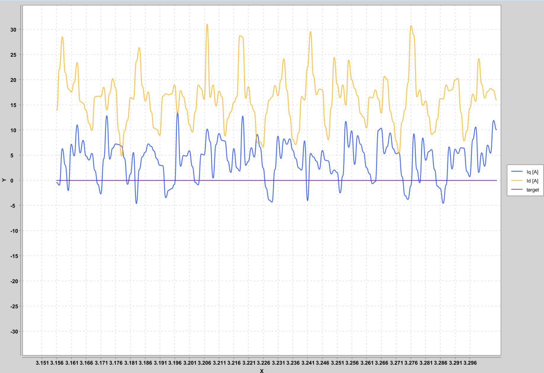
ok, but it’s not too noisy? I mean the noise is some Amperes, is not too much?
Yes, but that looks much higher than on the other plots, you changed something ?
No the only thing is that now was working in voltage mode and as before in torque control. The motor now draws 2Amps from the powersupply
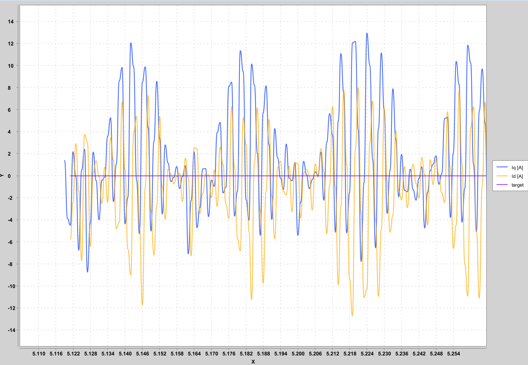
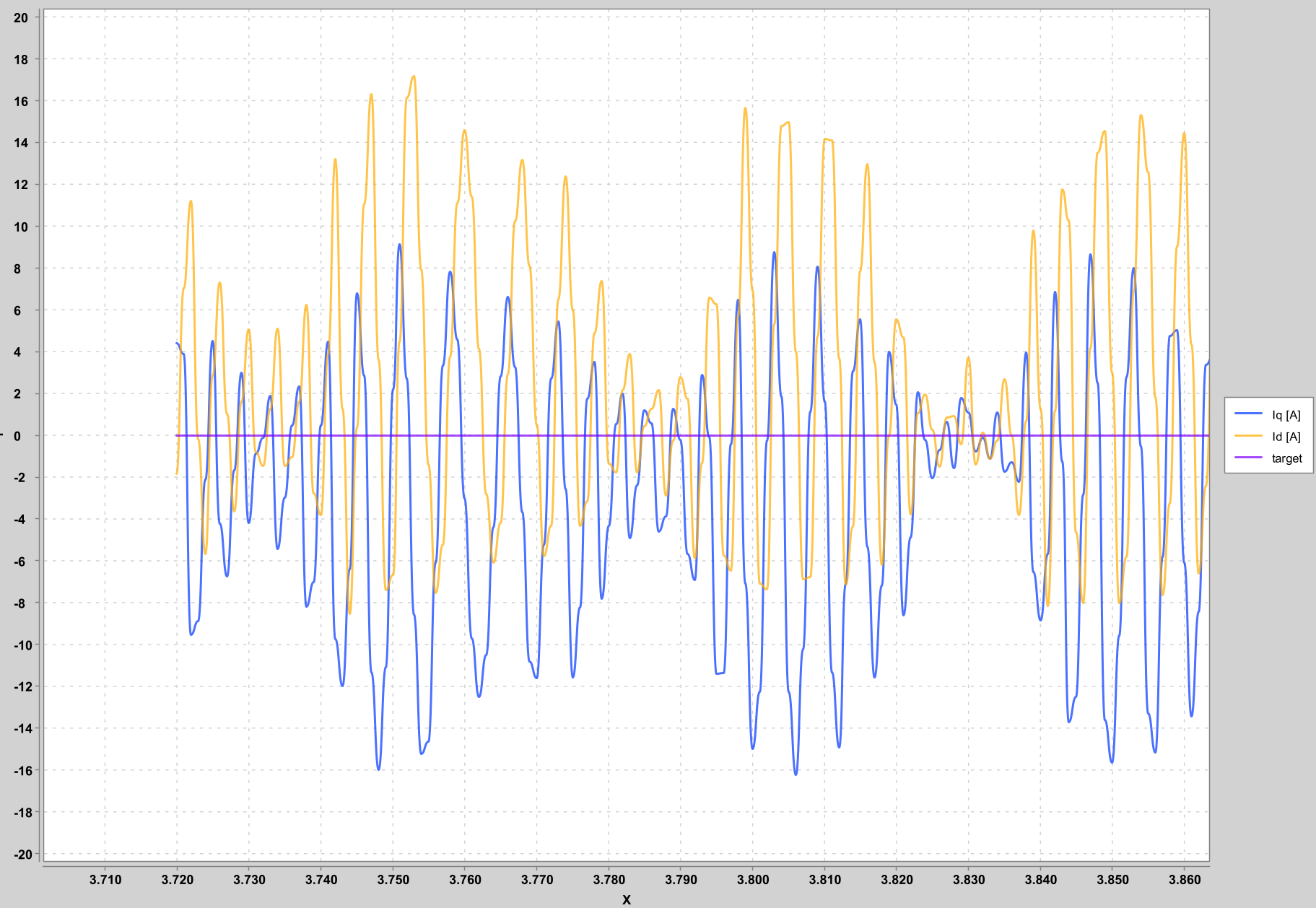
I’ve made some other tests in (voltage, torque mode) and when I stop the motor the currents get stables with noise and when I let it spin I get again the ac currents. Here a small video of how the currents behave when the motor turns and when I block it.
https://drive.google.com/file/d/1mlnLeQF3yUqxVWoQH449RoMDgoxOTx7f/view?usp=sharing
Are you sure about the phase current configuration?
Is the current sense align ok?
I think it’s correct. During the alignment I print the current readed during the alignement and during the test on the phase A (voltage on the a phase) I read ph_a current: -13.75A and on the phase B I get 6.8A so the system invert the sign of the gain_a and when it test the phase B I get ph_a: -6.75A and on phase_b: -14, so also in this case the system change the sign of the gain_b as result I get success 3 (change of the gains sign). There is a way to check if in this step something is not going correctly?
If you get success, it should be ok.
I can try to skip the align, put manually the signs on the gains and see if there some improvements on the currents
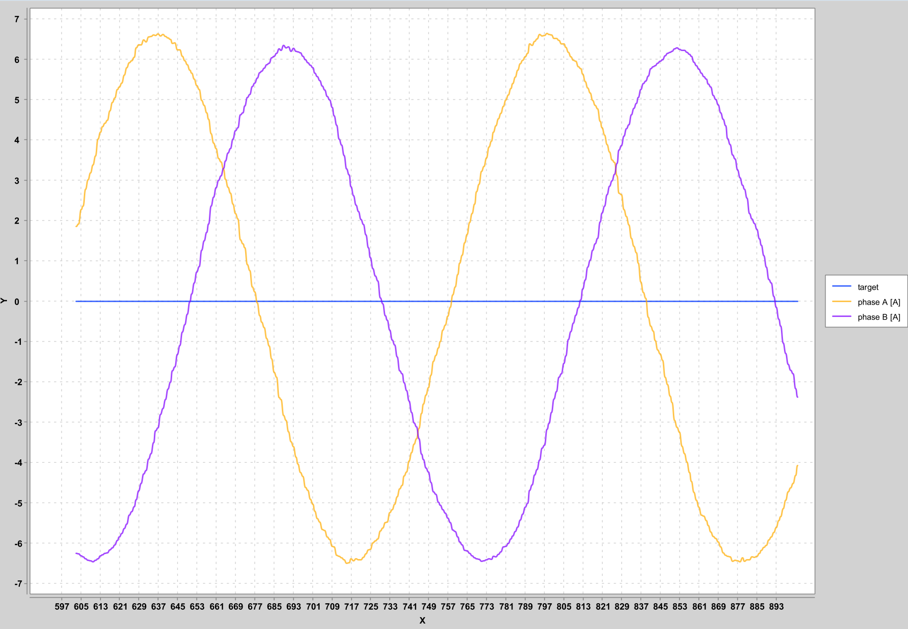
Can you plot phase a and phase b currents while running in velocity openloop slowly (0.5 rad/s) ?
Be careful to set a voltage_limit/current_limit that is low in this mode.
So I put the system in velocity openloop and I get this phases currents (0.5 rad/s), I set .
https://drive.google.com/file/d/1B147wTG7c8hwiUcsdF4eoFbpG8-z40Vc/view?usp=sharing
Well that looks ok.
The position/angle looked ok previously also.