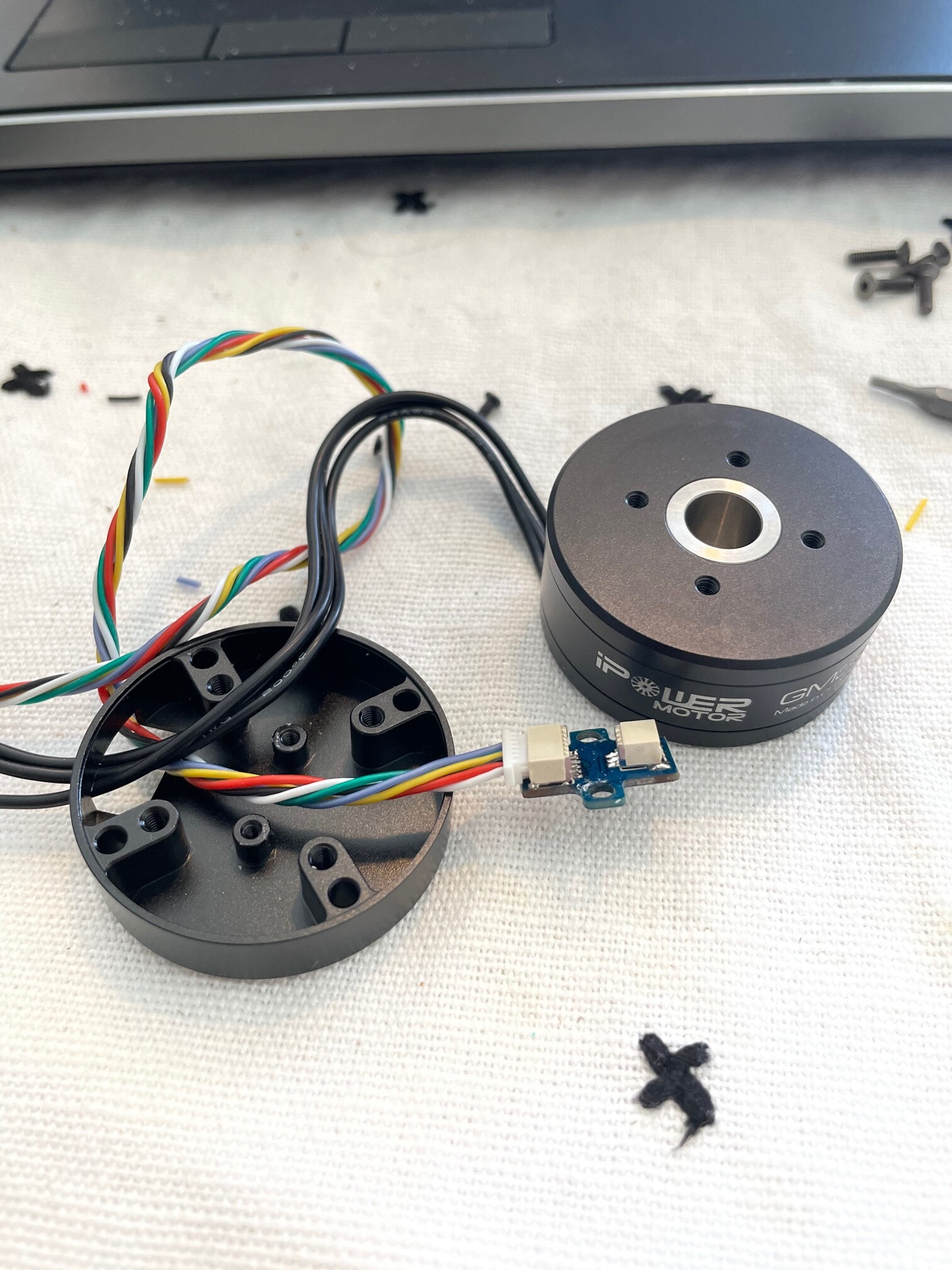
I am having a hard time finding information anywhere on the web on how to wire the magnetic encoder that I received with my motor from iPower. I have checked the datasheet from AMS, but when I try to follow the traces on the board to the 6 pin connector, I run into a few issues that don’t make sense to me yet. I cannot find a datasheet for this breakout board.
Anyways, I figured someone in here might have already solved this and be able to share their wisdom and save me the frustration I’m facing.
Your issue is that this is a non standard breakout board that is undocumented. A bit of a challenge but easily solved with a multimeter.
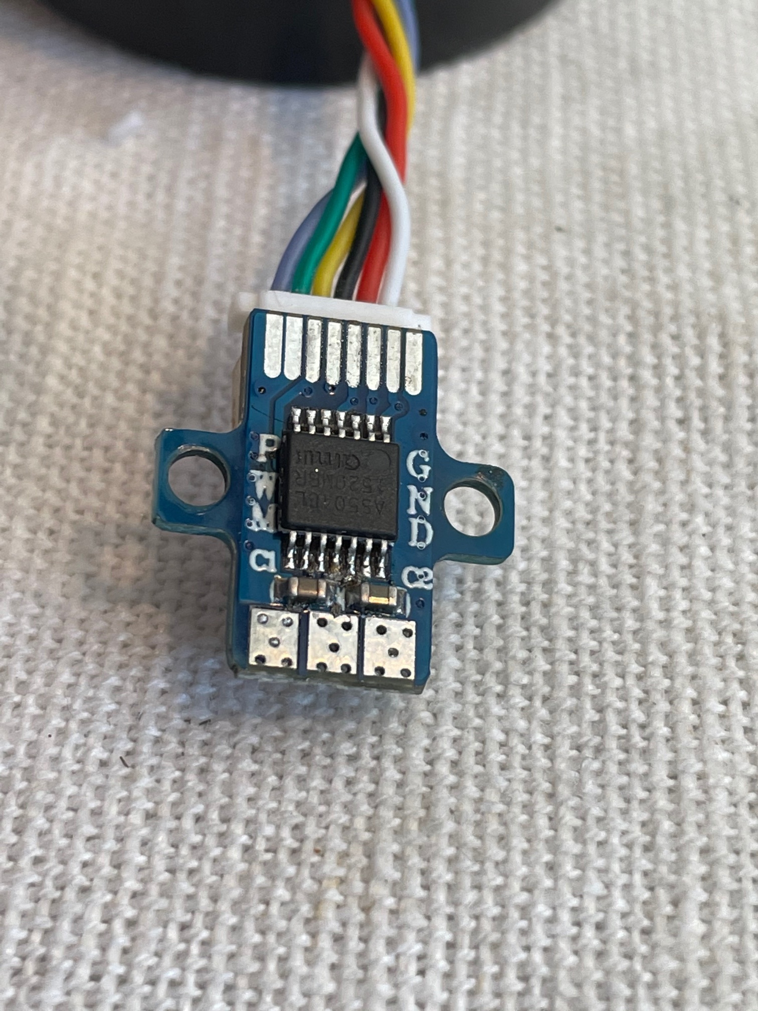
Do you know whether you have the A or B variant? I’m guessing A as there are 6 wires which matches what you’d expect fir SPI but it’s worth checking whether you can read what is written on the main chip.
Assuming A (spi) datasheet then I’d expect your 6 wires to be connected to 1 (chip select), 2 (clock), 3 (master in slave out), 4 (master out slave in), 13 (gnd) and either 11 or 12 for 3.3 or 5v.
First step is to work out which colour matches to which pin. I’d expect the wires to be directly connected to those pins, so switch to ohm-meter and look for zero ohms.
I wonder what the other connector is for? Is it a 4 pin connector or another 6pin?
Oof, I should have thought of that. On the website I purchased it from they list it as an ‘A’ variant, but the chip itself is marked ‘L’ interestingly. In case anyone else wants to save a few minutes, here’s how mine was wired:
I followed exactly the same procedure defined by Owen to find what color matches what pin.
I’m connecting this encoder to ESP32/ESP8266 boards and It doesn’t work.If I connect power to either 3.3V or Vusb (~5V), the ESP doesn’t even start. I even burned ESP32 trying it multiple times. I experienced it before only when I messed with polarity of the sensor. But here the polarity seems right to me.
So there must be something I don’t understand.
The main question - will it work at all? ESP8266/ESP32 have 3.3V digital logic, the green power pin is 5V, but the AS5048A encoder seems to be 3.3V compatible.
What power should I use?
2.1 Should I supply 5V to AS5048A (but SPI communication pins will be connected to 3.3V digital pins of ESP?)
2.2 should I connect 5V pin of AS5048A with 3.3 power supply in ESP?
2.3 . should I resolder green wire and supply 3.3V to AS5048A chip? (that could be tricky, it’s so small).
I have to say, this is strange… The sensor is not a high power device, and in my experience, even if you connect it wrong nothing much happens.
What you describe sounds like a short circuit, overloading the ESP32’s power regulator. You could use a multimeter check if any of the pins are unexpectedly connected (esp VDD to GND), both on the cable and the boards.
The wiring for 3.3V vs. 5V operation is slightly different for the AS5048… so if the board normally requires 5V, might have to power it that way. First thing to try is if it just works on 3.3V, since this will be easier. If not, you can power it with 5V and run the SPI with 3.3V, this should work. Really, you should add a voltage divider (or even better tri-state buffer) on the MISO line, since this will be driven by the sensor, but it will probably work without since the ESP32’s inputs are unofficially 5V tolarant (i.e. at your own risk, the datasheet says they aren’t but people use them that way).
My new ESP32 board is here and I soldered the +power pin directly to chip 3.3V. There was no other way to find 3.3V on PCB. And finally it works! Thanks!
I have the same setup: iPower motor + “integrated” AS5048A. I’m investigating why my sensor doesn’t seem to work (erratic readings).
I checked the wiring: it’s the same as what @bruhman described above. Notice that even though the chip supports VDD3V, the wiring only seems to allow for VDD5V.
Although things often work without all the specified caps, I think its really better to put them as recommended by the datasheet. Anything else is kind of asking for trouble.
Make sure your SPI speed is not too high. Start off at 1MHz, and see how high you can go before readings start to have errors.
You might want to look at this driver for the AS5048A. It supports reading the diagnostics and checking/clearing the error flag.
Another thing to try is grounding the unused pins like PWM…
Since you’re using the motor’s integrated magnet, it’s not going to be a magnet problem.
A logic analyser, even a very cheap one, can be a big help to find SPI communication problems…
If anyone also is trying to figure out the wiring for the “A” variant of the AS5048 that comes with a Power motor I can also confirm the same wiring as he got for the SPI port!
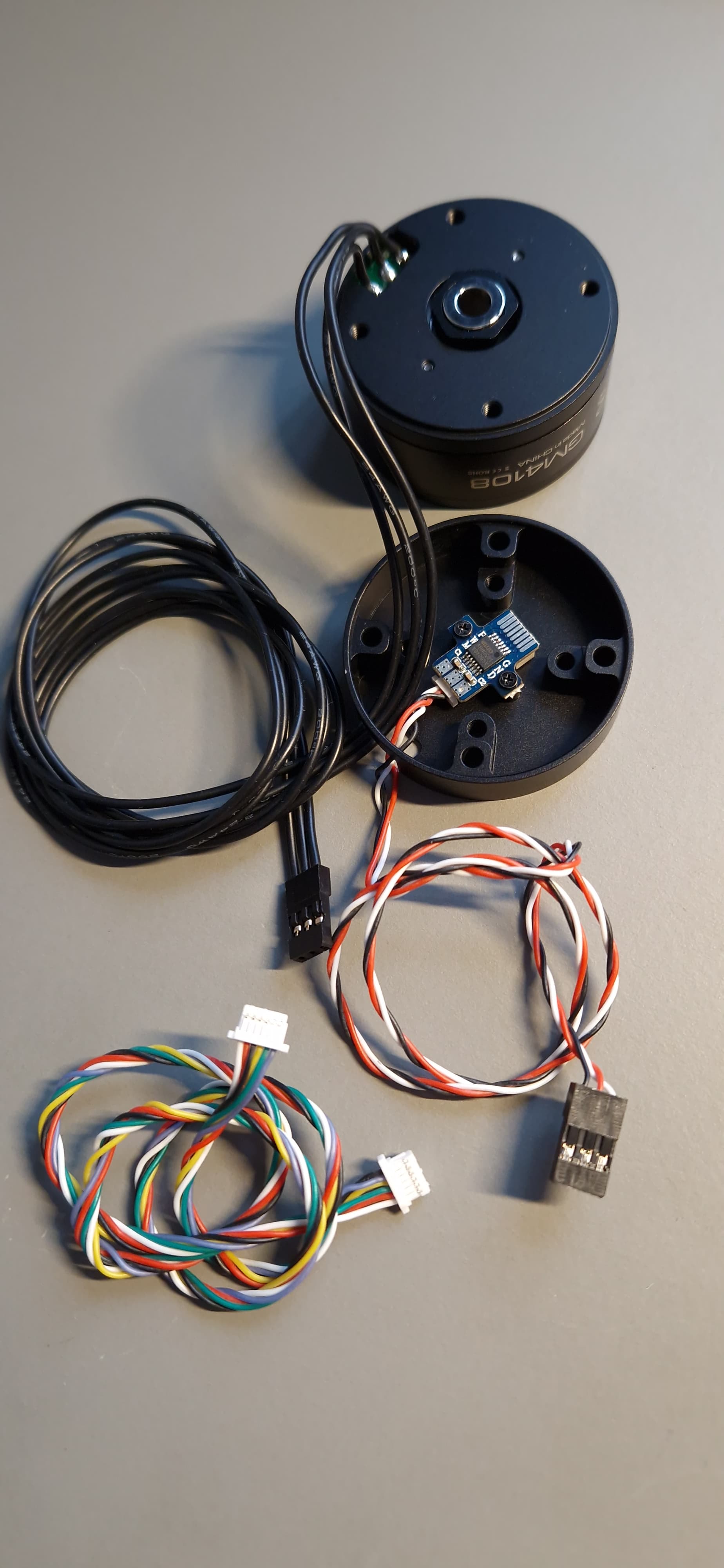
I 'd like to share more detailed information about the wiring of the AS5048A encoder integrated with an iPower GM4108 I just received from Aliexpress (https://de.aliexpress.com/item/1005003096568695.html) . This seems to be the same configuration shown above and below information might avoid some hustle for others:
The package includes two cables as shown, one with 3 pin female-female and one with 6 pin female-female connectors (seems to be JST-SH type). To use the SPI interface you will remove the 3 pin connector from the PWM output side of the breakout board and plug in the other cable into the 6 pin connector for SPI.
This other cable is not wired 1:1 as I would expect but connects white-red-black-yellow-green-blue on one side and black-blue-yellow-green-red-white on the other side. So if you use any color information of the 6 wire cable you have to be aware which end of the cable is plugged in.
I can confirm Brooks pin assignment confirmation stated above but it might read black-blue-yellow-green-red-white if you used the other side of the provided cable (pins of the connector read from the side marked with ‘GND’ on the breakout board).
With this wiring this motor runs immediately using SimpleFOCShield 2.0.4, Arduino Uno, and the ‘full_control_serial’ example (just replacing ‘AS5147_SPI’ by ‘AS5048_SPI’ as first argument for MagneticSensorSPI() )
Hi, Thanks a lot for this more detailed description. I still struggle to see how to connect the SPI to the simpleFOC shield board. Do you have a photo how you connect these and to which pins? Thanks so much @Kai-Krause
Please keep in mind that SimpleFOCShield just loops-through the pins used for SPI for an Arduino Uno form factor board. If the wiring does not work immediately I recommend to first connect the rotary encoder directly to your microcontroller board and test this first just with the encoder.
Had some troubles connecting magnetic encoder AS5048A included with iPower Motors to Arduino DUE via SPI (confusing colors, switched connectors, etc.).
Hi,
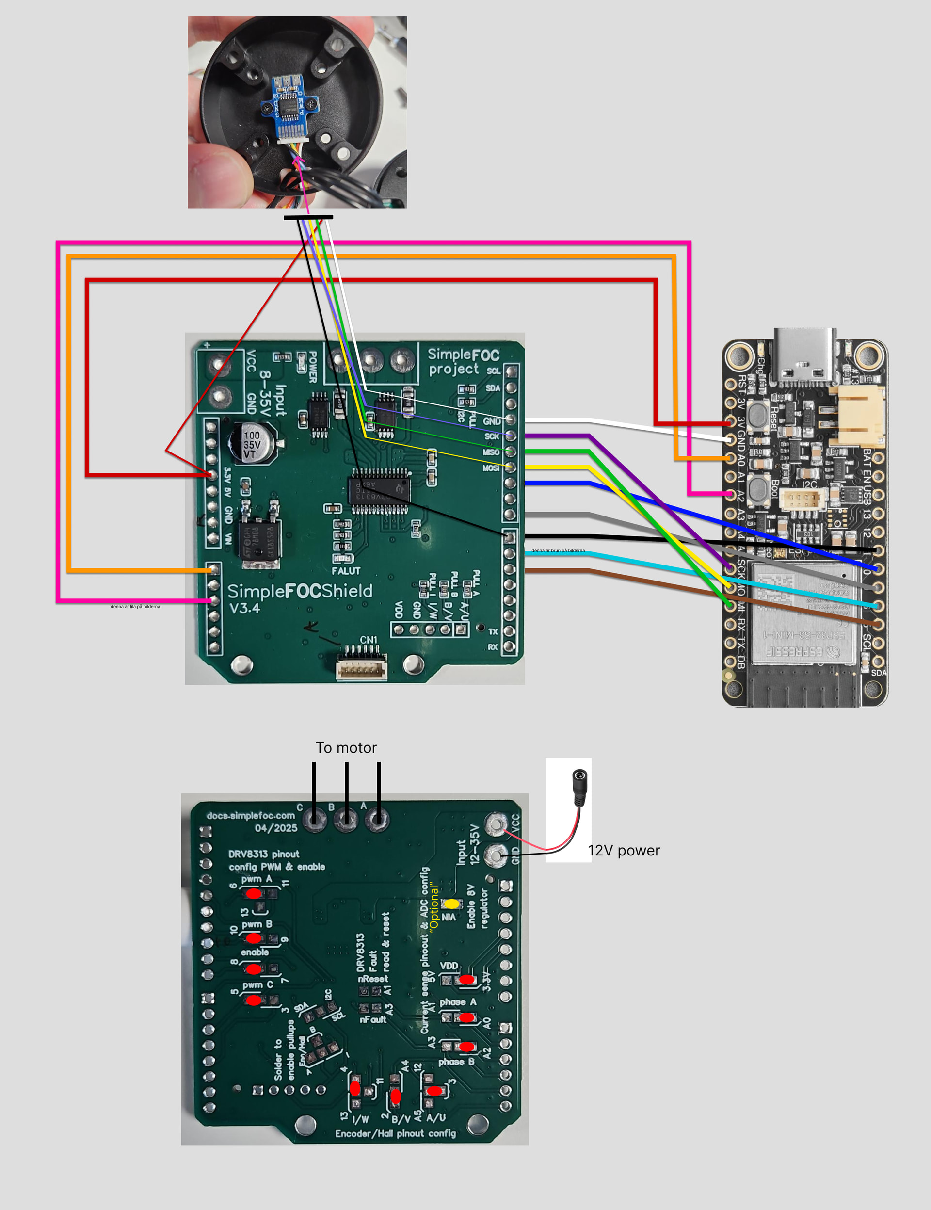
I got great help from this thread when connecting an esp32-s3 feather to the motor/encoder combo GM4108H-120T / AS5048A to a simpleFOC shield (v.3.4??). Attaching my coupling scheme for future reference.
Caveat I don’t really know what I’m doing, but it works for a force feedback application.
I have a very similar setup, and it does work, but my measurements are jittery. When I don’t touch the shaft (even power down the motor) there is quite a big spread in measurements. Like you, I power the AS5048a from a 3.3 pin. To troubleshoot, I tried to run it from a separate source. Increasing the voltage up to 3.7 improved the stability a lot, but any higher does not work at all. I thought I could power it by either 3.3v or 5v but I can’t get 5v to work. Has anyone seen something like this? Or is my device just cooked?