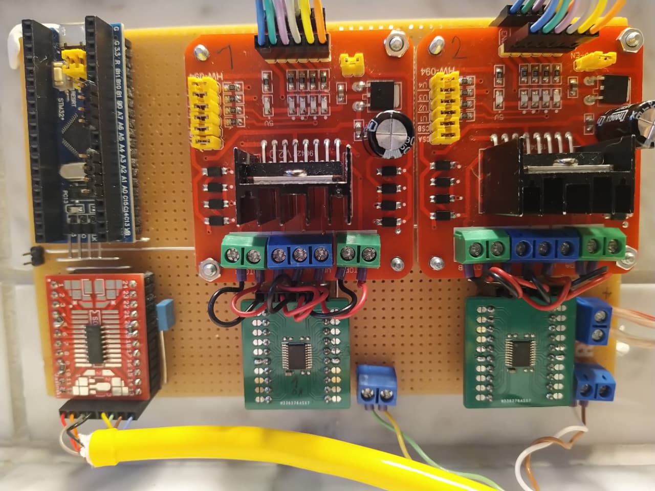
As I have to wait until Sep. 2022 to get the DRV8876 drivers for my board, I wanted to play with the software now and set up a test rigg with STM32 Bluepill, AS5147, two L298 in parallel mode with 330uF caps added, and two INA253 to measure the phase currents on a NEMA17 with R=1.3Ohm and 2.5A phase current. Goal is to have FOC for steppers.
Motor spins in open loop velocity mode (yeah!!) at 0.1rad/s, current limit set to 2.5A, power supply is 12V.
I recorded the INA253 output ( Vref set to 3.3V/2 )
The overall curve looks fine, it resembles the ±2A swing on the motor coil.
Now I have these questions:
Is the quality of this signal good enough for SimpleFOC ?
During the 24% duty cycle the current swings a lot around the average value by a value of 0.9A peak to peak. Here a zoomed picture showing back and forth currents over several scope sweeps:
At which positions relative to the overall cycle does SimpleFOC measure the currents? I could not derive that fom the code. Is it doing averaging? If yes, over which period?
What are the quality requirements on the phase current measurements regarding angle and amplitude to make SimpleFOC work fine?
Is some more filtering needed for the motor supply (2 x 330uF now), e.g. low value caps,
Is some filtering beneficial at the INA253 inputs ? I read in a forum that this chip might be not the perfect choice for PWM-style signals..
INA253 is a good choice for currents up to 15A. I’m not sure who/where you read this about PWM but this sensor is specifically designed for PWM applications.
Input filtering on an integrated resistor sensor is meaningless.
Yes, output filtering is probably beneficial, an RC low pass filter will benefit you. Very difficult to tell without the actual routed PCB and schematics. The oscilloscope shots are beautiful but of limited value since we don’t know what drove them. The PCB layout is really crucial.
In inline current sense scheme the position doesn’t matter really. It matters only when doing low or high side measurements. Perhaps someone familiar with the code could provide more input on this.
Not following you here, could you please elaborate?
Giving you the politically correct answer, it depends. Voltage, current, motor, resistance, PWM frequency, this is a complicated question. Generally you need at minimum an RC snubber and a buffer capacitor working together. Give us more details on these and you may get an answer.
In general INA253 can deal with PWM, but there are limits in bandwidth. I can’t judge if our scenario is critical.
My problem is that I don’t have a current or differential probe to see what is really going on in the motor. So can I believe what I see on INA253 output? Maybe it is totally ok. If somebody could provide a reference with all relevant signals recorded and related to code timing that would really improve the understanding of the whole story. Coming from microstepper controllers with integrated current chopping it is somewhat hard to transition to FOC principles..
INA253 has pins to do input filtering, but normally they are not used and filtering seems to be source for trouble.
RC on ouput - not bad… I could check that on my test board. It is a soldered breadboard which has nothing to do with the “final” PCB I already have for DRV8876. But in both cases the INA253 outputs are directly connected to BluePill ADC pins. The INAs are here on the green boards, the L298 are just commercial ones where I added 330uF. No RC snubbers.
What I understood about FOC up to now: to run the FOC algorithm we need to know the axis position (encoder) and the electrical angle → phase of the currents. The measured value of currents can be used to limit them by adapting the PWM duty cycle. The angle goes into the formula…
But how often and when per RPM is this calculation done? Is it done at each PWM pulse I see ? then I wonder how to deal with this oscillation I see when the bridge is open for e.g. 10us. Or is the median over e.g. 1 ms taken and I can just look on a calm, RC filtered current signal? Somehow I miss the link from current measurement in time to an electrical angle..
The PWM pulses happen (this depends a bit on the hardware setup) at several kHz, lets say 30kHz. For FOC control, is good to run the FOC loop as often as possible, but on most setups, esp. if you include current sensing as well you won’t get quite the same speed as the PWM frequency - lets say a few kHz, depending on the MCU.
But it also doesn’t really make sense to set the PWM level after every PWM period, and it certainly doesn’t make sense to set the PWM levels more often than the PWM period.
The FOC loop can only update the PWM values if there are new sensor values, so that will also limit the performance of the FOC loop.
As I tried to describe above it isn’t fixed, and isn’t synchronized to the PWM. The more often the better, but it doesn’t make sense to go faster than the PWM frequency.
When doing inline current sensing, the current sensing does not really need to be coordinated to the PWM frequency (this is in contrast to low-side current sensing, where it is important to synchronize it to the PWM on-periods of the low-side FETs). However, it would be nice to get new values once every FOC loop, which is what the code currently does.
Note that the current sensing doesn’t need to be so fast - the PWM speed is expected to be such that we get several PWM periods for each PWM level set. The PWM levels are set by the FOC loop, provided there are new sensor values. The FOC loop is expected to execute several times (>10, ideally) per electrical revolution, and the current changes we are trying to measure track the electrical revolutions.
If you’re trying to do current limiting in terms of protection circuits, then you would have to measure very quickly, and it is doubtful whether it’s a good idea to do this via a MCU. A dedicated comparator would be much faster. If you’re trying to do inline current sensing, the signal you’re measuring is changing at the speed of the electrical revolutions, and you only need new values once per FOC loop…
You realize they are trying use INA253 to measure switching frequency of 800kHz, which is close to 1MHz, right? On a sensor that’s specced at 350KHz bandwidth? Whoever tried to do this was smoking something so good I want some of it, too. See for yourself:
That’s a good one. However, I’d go a step further and offload the current limiting to a fast hardware solution, rather than rely on the MCU. Or get a driver that current-limits on a built-in silicone level.
Oh, look, what a surprise, the DRV8876 driver allows for current limit to be set with an adjustable external voltage reference. Section 7.3.4.3 OUTx Overcurrent Protection (OCP) from the documentation, page 16.
I know that DRV8876 has these capability. But I was unsure if this interferes with what SimpleFOC does in terms of current limiting. If I set motor.current_max to e.g. 2.5A (motor has 1.3Ohms per coil) in openloop velocity mode, it does a good job in limiting the duty cycle for the L298 which does not have limiting capability without a L297. Are there really CPU resources freed when I use DRV8876 instead L298? I don’t see an option “disable current limiting”. I thought it is always either voltage limited (when no sensor) or current limited (when sensor available). I agree that if MCU is offloaded, using the driver’s features is a goal.
Peter
SimpleFOC does nothing in terms of active current limiting, so as Ostap Bender said, the task of saving the drowning people is in the hands of the drowning people themselves [https://proza.ru/2007/02/12-319]. The algorithm is trying to control the current based on the sensed current, only for motor control, not to protect your hardware, however, the fast transient events are not part of the limiting algorithm, and if you get a surge, your only line of defense is the built-in ultra-fast hardware limiting outside. Having multiple, cascading lines of defense is a good practice. Please consider using the driver’s feature to its maximum.
I had noticed that they talked about 800kHz which is clearly beyond specs. But being more a digital than analog guy, I was wondering if even 25kHz or 50kHz PWM would create problems due to steep rise/fall times.
The sensor is designed to handle exactly that use case. From the documentation, page 1:
The INA253 is designed with enhanced PWM
rejection circuitry to suppress large (dv/dt) signals
that enable real-time continuous current
measurements. The measurements are critical for
inline current measurements in a motor-drive
application, and for solenoid valve control
applications.
The large (dv/dt) signals means the sharp rise/fall of the PWM square signal, both positive and negative derivatives.
You know what would be a very cool feature in simpleFoCStudio. A Mosfet calculator, kinda like the trace calculator in KiCad. It should rely on formulas for calculating heat development if using X on_resistance, X heat_dessipation, X watt to board, air and so on… Furthermore it should calculate cap´s and resistors for implementing a suitable low cost 6 pin pwm driver.
Too complicated. Simply add a one penny NTC and measure the temperature directly from one of the analog inputs. Heat buildup simulation is extremely complicated.
I mean, wasn´t that huge telescope delayed already. That´s wright, their plan is to setup camp on Mars when the Golf collapses. That´s a f* stupid plan. You know where they should point that thing. The great attractor. Then the clock will start ticking. There are some question… [split] var >>> plot
Oook, that explains some things. So for L298 experiments i am working with one weak line of defense and when switching to DRV8876 (when those f* chips will ever be available) I can rely on a second, much better line of defense.
And current sampling frequency is fine enough as long as it is >10 per el. rev. and is linked 1:1 to the FOC loop frequency. And that means that the FOC loop freq. limits the max. RPM of the stepper.
By the way - when the stepper has 50 pole pairs, how are el. revs. related to physical revs?


")