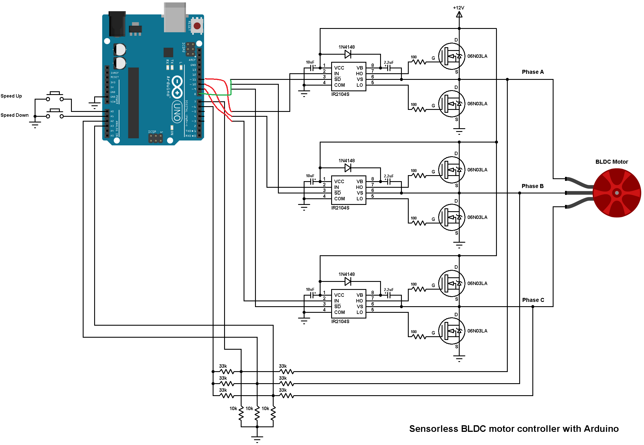
The IR2104 driver is a single PWM input with a HIGH enable shutdown. Why do you have the SD pins taking PWM from 9,10,11 ?
Tie up all three SD to a single arduino pin, for example, 8 for driver enable function and tie the three IN to the 9, 10 and 11 each respectively.
Then the code will be something like
BLDCDriver3PWM driver = BLDCDriver3PWM(9, 10, 11, 8);
Also the code example you posted is just a static PWM test, you need to load the open loop example, that’s different code.
Cheers,
Valentine