Hi Guys, I have a bldc motor setup with arduino and a basic driver. In the hopes of achieving Foc I tried the standalone 6pwm code. and there is no moment in the motor. I tested the voltage on the pwm pins and few pins do not have any voltage on them and the others are not generating any pwm, They are giving out a stable voltage of 1.8v - 2v. Can someone help me with getting pwm signals on the output pins of arduino uno.
// pwm frequency to be used [Hz]
// for atmega328 fixed to 32kHz
// esp32/stm32/teensy configurable
driver.pwm_frequency = 50000;
// power supply voltage [V]
driver.voltage_power_supply = 12;
// Max DC voltage allowed - default voltage_power_supply
driver.voltage_limit = 12;
// daad_zone [0,1] - default 0.02f - 2%
driver.dead_zone = 0.05f;
I would start trying to make it working using a BLDCDriver3PWM for simplicity instead of BLDCDriver6PWM and testing with an oscilloscope if you are able to get PWM signals.
I tried the 3 pwm setting but the motor isnt turning, Its beeping but not turning. I also connected a AS5600 Magnetic encoding sensor behind the motor shaft. I’m getting the angle and velocity on the serial monitor, but when I run closed loop or open loop or any other code focusing on rotating the motor it isn’t working.
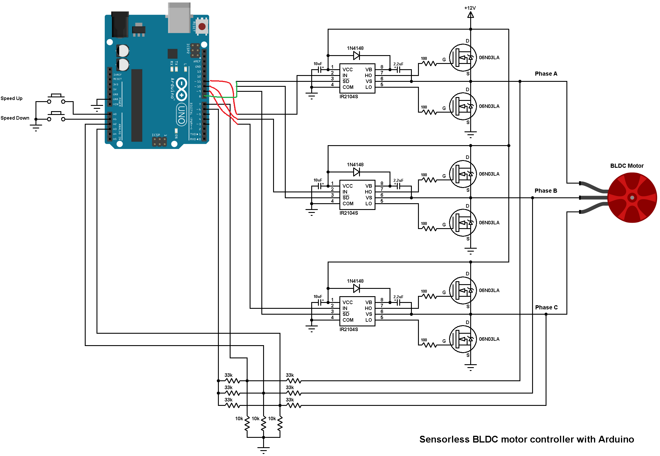
I want to change the driver but I have no time to do so. Can you please help me with getting the motor turn with ir2104s driver. Is it even possible to do so in the first place?
Ok, if open loop is not working, then it is a sign that this is an electrical problem or a problem with the PWM generation.
First thing to check is the PWM generation. It is best to do this with the motor power switched off, to prevent problems.
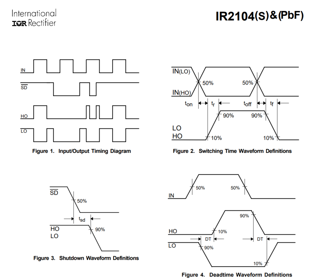
Do you have an oscilloscope or logic analyser? Then you can check each of the 3 PWM pins, using the 3-PWM mode. You can use the code like you posted, and use driver.setPwm(3,6,9); - then you should see 3 PWM waves on pins 5, 6 and 9, with duty cycles of 25%, 50% and 75%.
Please also comment out the line // driver.pwm_frequency = 50000; and leave it at the default setting for now.
I do not know the details of your driver board. If you have a circuit diagram or other information it could be helpful.
But in terms of the IR2104, if you can control its IN and SD pins, then yes, it should be possible to use BLDCDriver3PWM with these drivers, no problem.
This is the driver circuit that I’m using. I would’ve gone with simplefoc drivers, but I have a budget constrain. Getting Drv driver in india is pretty hard.
Something that you could try is checking that the cables make good contact by checking that there is a signal at both ends of them and make sure that the Arduino GND is connected to the GND of the driver board.
Can you remove all your voltage dividers at the bottom? I’m not sure why you have them all tied with one pin also, are you trying to bias it? They might be causing an issue. If you want to do in-line current sensing, it should be like this:
That one is a voltage sensing circuit, and it can just be ignored. SimpleFOC does not use it, but it also shouldn’t bother anything. No need to change it.
I don’t have a logic analyser, I tested the outputs with a Multimeter and there is a very stable voltage of 8v at the phase output of the bldc driver.
I don’t think any pwm is being generated.
No, its not mandatory, but if you say the wiring is correct, and the open loop is not working, then we should find out why…
The first step to know is if the PWM is being generated correctly. If yes, then the problem will be with the driver stage. If there is no PWM then it is a MCU/Software problem…
I Tested arduino with an oscilloscope, It had the Open loop example running up in it. There were
pwm signal in pins 9, 10 ,11 and no moment in 3, 5, 6 .What to do?