I am currently trying to work with a stepper motor. I recently discovered SimpleFOC and since then I am trying to understand how it works.
But that’s not the question for this thread. I am wondering how I can mount an encoder to my motor. I have bought a NEMA 34 Motor without an encoder but now I want to integrate one - but how?
You can see I’ve glued a diametric magnet to the shaft. It ‘really’ helps if your motor exposed it’s shaft at the back like mine does. So I’ve removed the 4 m3 bolts - i had to buy slightly longer m3 ones to account for the two part orange plate that holds the as5600 magnetic sensor approximately 2mm from the magnet.
The orange plates that house the sensor were designed with openscad, but others will prefer fusion360 or onshape. Printed on an ender 3 with petg.
I’m not a fan of the as5600. Here is a nema with an as5047u or p (can’t remember which). It is £12 instead of £3 but much easier to work with
@santosh I was just wondering in general. I’ve read about all these kind of different types of encoders (magnetic, optical,…) but I didn’t really see a possibility to mount it.
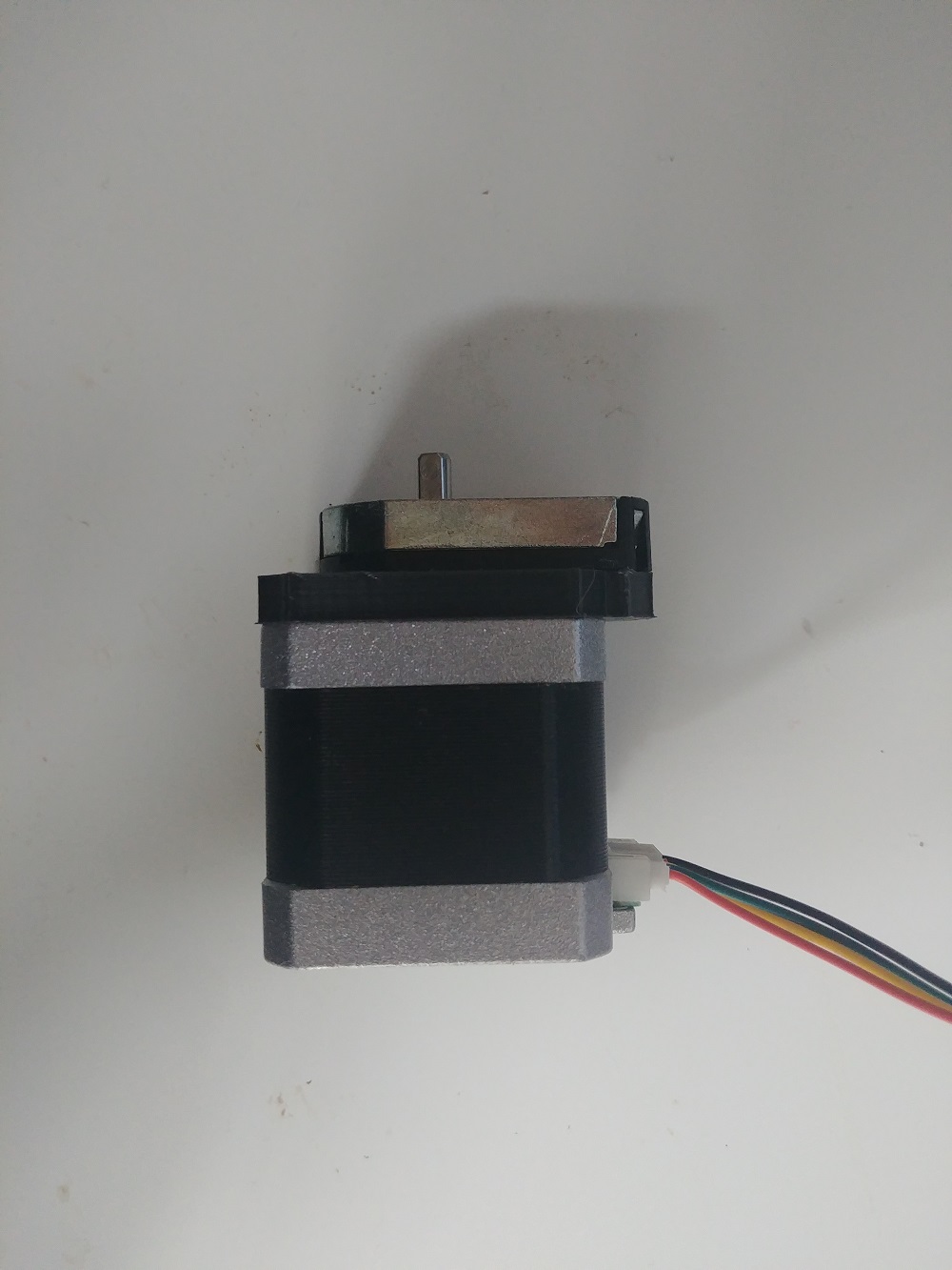
@Owen_Williams that helped me a lot. I bought a NEMA 34 like this:
So I hope that the back side has a hole for the shaft, but if not - do I have to drill a hole in the back?
And would I mount an optical encoder in this similar way like your magnetic one?
If you do not have an easy access to the shaft from behind I think you’ll need to mount it on the front side.
I’ve done that using a simple 3D printed part as well. I was using an encoder AMT102-V Which is very easy to mount and belongs to the field of the cheaper incremental encoders.
thank you very much! I didn’t order a closed loop stepper, because I’ve read, that the resolution of the integrated encoders shouldn’t be so good (at least if you are looking for a cheap one).
The project I am working on is a Steering wheel. The motor I will be using is linked in the post above, currently I am using an arduino uno but this is just for getting familiar with motors, motor drivers and encoders in general. Later I will be using a PLC from Beckhoff.
At first I was using a A4988 but the problem with this one was, that you can only adjust the current by a screw and it is important for me to control the torque.
So right now I’ve ordered a L289N Driver like in your example but a future problem with this one could be the high currents of my 5.6 A motor
That sounds like a very interesting project! You should be able to test in angle_openloop control mode (without sensor) and can control the current using voltage_limit. Later you can close the loop by adding a sensor. Openloop doesn’t require PID tuning so is a simple first step but, of course, won’t know if the motor ‘slips’ out of position.