How many pole pairs?/ Checking timers

Hello!

I wanted to find out numer of pole pairs of my motor, so I screwed the motor into the drill and turned it to 840rpm, between two phases I measured 99Hz, so there should be 60*99/840=7 pole pairs, right?

Then I connected to velocity openloop, set 7 pole pairs and motor.target=10

I started measuring velocity

  if (currentMillis - previousMillis >= 1000) {
    previousMillis = currentMillis;

    static float a;
    static float a_prev;
    a = sensor.getAngle();
    float w = (a_prev-a);
    Serial1.println(w);
    a_prev = a;

  }

image

I’m getting w~20, like it should be 3,5 pole pair?
it is measured every 1 second (checked it)
what’s wrong then?
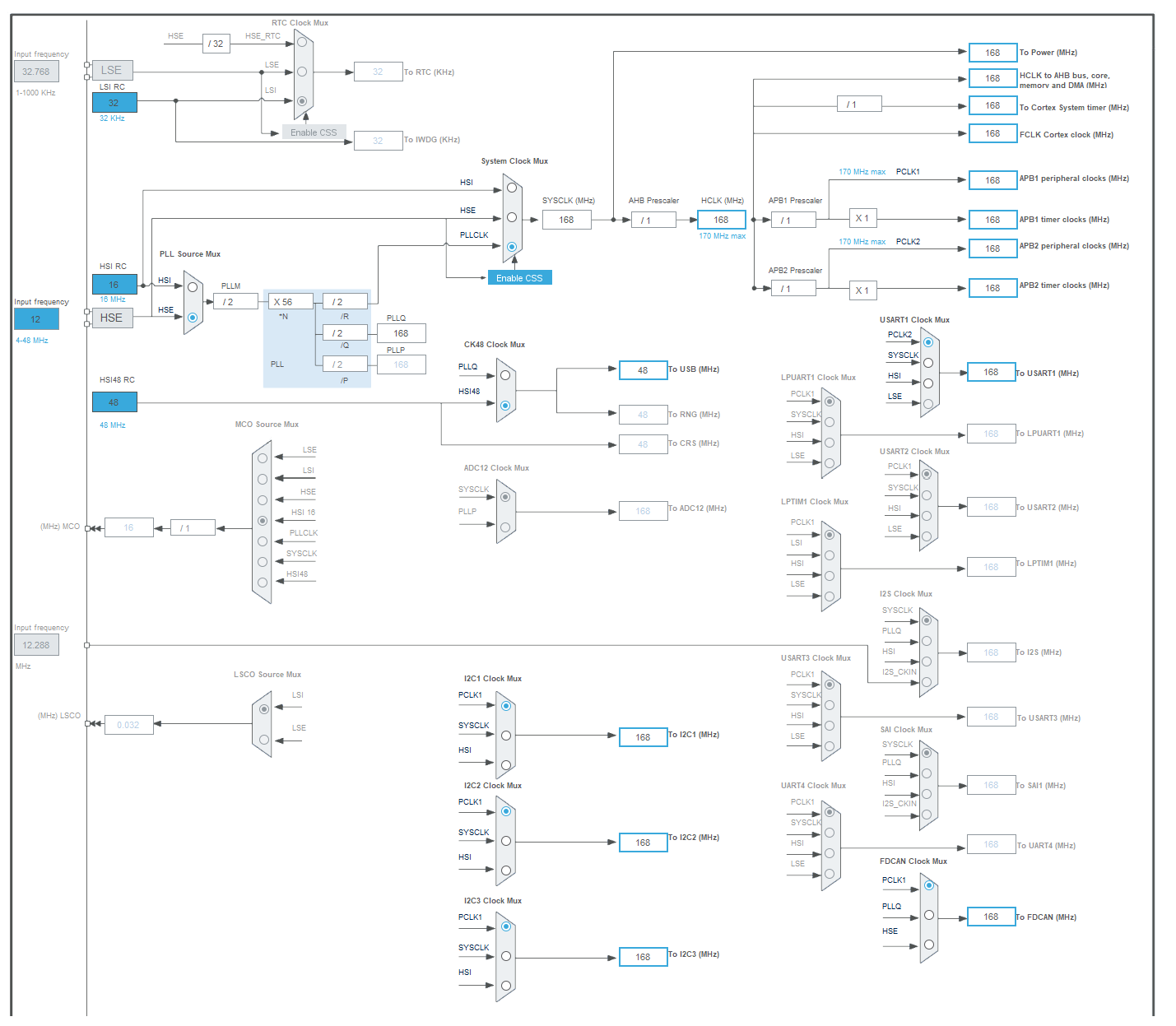
i’m using -D HSE_VALUE=12000000U
but without it behaves like it’s made for 24MHz, so maybe library timers are set for that clock?
how can i check and change it?

usart, delays, millis works well

[env:genericSTM32G431VB]
platform = ststm32
board = genericSTM32G431VB
framework = arduino
board_build.ldscript = ./variant/ldscript.ld
upload_protocol = stlink


lib_archive = false

monitor_speed = 115200
monitor_eol = LF

build_unflags = -Os
build_flags = 
    -Ofast
	-D SIMPLEFOC_STM32_DEBUG
    -D ARDUINO_GENERIC_G431VBTX
    -D HSE_VALUE=12000000U 
    -D ARDUINO_GENERIC_G431CBUX
    -DSERIAL_UART_INSTANCE=1
    -D HAL_OPAMP_MODULE_ENABLED

    -DSIMPLEFOC_STM32_DEBUG
	-DPIO_FRAMEWORK_ARDUINO_ENABLE_CDC
    -DUSBD_USE_CDC
    -DUSBCON


lib_deps =
    adafruit/Adafruit NeoPixel@^1.11.0
/**
  * @brief System Clock Configuration
  * @retval None
  */
void SystemClock_Config(void)
{
  RCC_OscInitTypeDef RCC_OscInitStruct = {0};
  RCC_ClkInitTypeDef RCC_ClkInitStruct = {0};
  RCC_PeriphCLKInitTypeDef PeriphClkInit = {0};

  /** Configure the main internal regulator output voltage
  */
  HAL_PWREx_ControlVoltageScaling(PWR_REGULATOR_VOLTAGE_SCALE1_BOOST);
  /** Initializes the RCC Oscillators according to the specified parameters
  * in the RCC_OscInitTypeDef structure.
  */
  RCC_OscInitStruct.OscillatorType = RCC_OSCILLATORTYPE_HSI48|RCC_OSCILLATORTYPE_HSE;
  RCC_OscInitStruct.HSEState = RCC_HSE_ON;
  RCC_OscInitStruct.HSI48State = RCC_HSI48_ON;
  RCC_OscInitStruct.PLL.PLLState = RCC_PLL_ON;
  RCC_OscInitStruct.PLL.PLLSource = RCC_PLLSOURCE_HSE;
  RCC_OscInitStruct.PLL.PLLM = RCC_PLLM_DIV2;
  RCC_OscInitStruct.PLL.PLLN = 28;
  RCC_OscInitStruct.PLL.PLLP = RCC_PLLP_DIV2;
  RCC_OscInitStruct.PLL.PLLQ = RCC_PLLQ_DIV4;
  RCC_OscInitStruct.PLL.PLLR = RCC_PLLR_DIV2;
  if (HAL_RCC_OscConfig(&RCC_OscInitStruct) != HAL_OK)
  {
    Error_Handler();
  }
  /** Initializes the CPU, AHB and APB buses clocks
  */
  RCC_ClkInitStruct.ClockType = RCC_CLOCKTYPE_HCLK|RCC_CLOCKTYPE_SYSCLK
                              |RCC_CLOCKTYPE_PCLK1|RCC_CLOCKTYPE_PCLK2;
  RCC_ClkInitStruct.SYSCLKSource = RCC_SYSCLKSOURCE_PLLCLK;
  RCC_ClkInitStruct.AHBCLKDivider = RCC_SYSCLK_DIV1;
  RCC_ClkInitStruct.APB1CLKDivider = RCC_HCLK_DIV1;
  RCC_ClkInitStruct.APB2CLKDivider = RCC_HCLK_DIV1;

  if (HAL_RCC_ClockConfig(&RCC_ClkInitStruct, FLASH_LATENCY_4) != HAL_OK)
  {
    Error_Handler();
  }


  //Initializes the peripherals clocks
 
  PeriphClkInit.PeriphClockSelection = RCC_PERIPHCLK_USART1|RCC_PERIPHCLK_I2C1
                              |RCC_PERIPHCLK_I2C2|RCC_PERIPHCLK_I2C3
                              |RCC_PERIPHCLK_USB|RCC_PERIPHCLK_ADC12
                              |RCC_PERIPHCLK_FDCAN;
  
  PeriphClkInit.Usart1ClockSelection = RCC_USART1CLKSOURCE_PCLK2;
  PeriphClkInit.I2c1ClockSelection = RCC_I2C1CLKSOURCE_PCLK1;
  PeriphClkInit.I2c2ClockSelection = RCC_I2C2CLKSOURCE_PCLK1;
  PeriphClkInit.I2c3ClockSelection = RCC_I2C3CLKSOURCE_PCLK1;
  PeriphClkInit.FdcanClockSelection = RCC_FDCANCLKSOURCE_PCLK1;
  PeriphClkInit.UsbClockSelection = RCC_USBCLKSOURCE_HSI48;
  PeriphClkInit.Adc12ClockSelection = RCC_ADC12CLKSOURCE_SYSCLK;

  if (HAL_RCCEx_PeriphCLKConfig(&PeriphClkInit) != HAL_OK)
  {
    Error_Handler();
  }
}

I tried to change

RCC_OscInitStruct.PLL.PLLM = RCC_PLLM_DIV2;

to

RCC_OscInitStruct.PLL.PLLM = RCC_PLLM_DIV1;

with deleting -D HSE_VALUE=12000000U but then STM stops and doesn’t do main loop :smiley:

What motor do you have? There should be easier methods?

It can’t have a half-pole pair, so that isn’t right. On my boards I had also an issue with the wrong clock being used, but pole pair check still worked ,so I don’t think this has that much dependence on peripheral clock. After all, the clock that it “thinks” it has is different from what is actually being piped into the PLLs. So if you did not touch the default clock config, but you adjusted the HSE_VALUE, then things will be off. Instead of tinkering with the clock config, I would just generate your own clock config with CubeIDE/ CubeMX/ by hand, and just drop that in your project src directory, as SystemClock_Config should have a weak binding in the library.

Yes, the Nucleo boards come with 24MHz clock (even though it is usually unpopulated…) so this is the default in STM32duino, you need to overwrite it with the build flag like you showed.

When i’m trying to change divider from 2 to 1 (12MHz crystal) or solder 24MHz and keep divider 2 program stops at :upside_down_face:

motor.initFOC(); 

INTRIGUING

For the clock setup, I recommend using STM32CubeIDE to generate a working clock setup, and then copy the generated function to your sketch. Otherwise you can spend a lot of time trying different options and rebooting each time…

In any case having the clock wrong would only result in a different PWM frequency than expected, this should not normally impact the behaviour enormously (unless it is way off, by a factor of 10 or something). The algorithms will run faster or slower depending on the clock, and this will affect how many iterations per second you get - which can have an impact on performance also, but as long as you’re getting 1000 iterations per second or more, commutation should be possible.

Finally, if the clock were misconfigured so that microseconds/milliseconds timers give incorrect time, you would notice this with your test code, which is printing 1x per second. If it’s only printing every 2s, you have a serious problem :wink:

Could you check if it is everything okay with my clock setting? Or maybe i need some build_flag? Because it doesn’t work, stm does nothing after those lines (without them it goes with i guess some standard clock setting and works)

It stops at first Error_Handler(); (i’m doing it is void setup)

  RCC_OscInitTypeDef RCC_OscInitStruct = {0};
  RCC_ClkInitTypeDef RCC_ClkInitStruct = {0};

  /** Configure the main internal regulator output voltage
  */
  HAL_PWREx_ControlVoltageScaling(PWR_REGULATOR_VOLTAGE_SCALE1_BOOST);

  /** Initializes the RCC Oscillators according to the specified parameters
  * in the RCC_OscInitTypeDef structure.
  */
  RCC_OscInitStruct.OscillatorType = RCC_OSCILLATORTYPE_HSI48|RCC_OSCILLATORTYPE_HSE;
  RCC_OscInitStruct.HSEState = RCC_HSE_ON;
  RCC_OscInitStruct.HSI48State = RCC_HSI48_ON;
  RCC_OscInitStruct.PLL.PLLState = RCC_PLL_ON;
  RCC_OscInitStruct.PLL.PLLSource = RCC_PLLSOURCE_HSE;
  RCC_OscInitStruct.PLL.PLLM = RCC_PLLM_DIV2;
  RCC_OscInitStruct.PLL.PLLN = 56;
  RCC_OscInitStruct.PLL.PLLP = RCC_PLLP_DIV2;
  RCC_OscInitStruct.PLL.PLLQ = RCC_PLLQ_DIV2;
  RCC_OscInitStruct.PLL.PLLR = RCC_PLLR_DIV2;
  if (HAL_RCC_OscConfig(&RCC_OscInitStruct) != HAL_OK)
  {
    Error_Handler();
  }

  /** Initializes the CPU, AHB and APB buses clocks
  */
  RCC_ClkInitStruct.ClockType = RCC_CLOCKTYPE_HCLK|RCC_CLOCKTYPE_SYSCLK
                              |RCC_CLOCKTYPE_PCLK1|RCC_CLOCKTYPE_PCLK2;
  RCC_ClkInitStruct.SYSCLKSource = RCC_SYSCLKSOURCE_PLLCLK;
  RCC_ClkInitStruct.AHBCLKDivider = RCC_SYSCLK_DIV1;
  RCC_ClkInitStruct.APB1CLKDivider = RCC_HCLK_DIV1;
  RCC_ClkInitStruct.APB2CLKDivider = RCC_HCLK_DIV1;

  if (HAL_RCC_ClockConfig(&RCC_ClkInitStruct, FLASH_LATENCY_4) != HAL_OK)
  {
    Error_Handler();
  }

If STM32CubeIDE does not complain about it, then it should be a working setting… e.g. it shouldn’t really crash.

You should not call these in setup, you should copy the whole clockSetup function into your sketch. Otherwise it will first run the default clockSetup, and then the code in your setup(), and it might not be a good idea to run both.

it looked like the crystal oscillator was on stability limit or sth, I changed divider from 1 to 4 and multiplicator from 56 to 14, now works on 24MHz crystal

still velocity is 2 times bigger than motor.target, i’m almost sure how much pole pairs are there, so what can be wrong?

But if you increase the divider by a factor of 4, and decrease the multiplier by a factor of 4, then you have lowered the clock speed by a factor of 16?

it’s your sensor. Is it an encoder? Decrease the PPR setting to half its current value.
Is it a magnetic sensor? Something is wrong with the bit-positions or SPI mode.

No, because at first crystal frequency is divided, then multiplicated, it is still the same

Yeah, You were right, revolution gives me 4pi, I was sure I checked it before… thanks!

1 / 1 * 56 = 56
1 / 4 * 14 = 3.5

:slight_smile:

1 Like