But is it working then
It could be missing interrupts
I tested the hall sensor and found that by turning the wheel once, the angle reached 6.28rad
And no steps were missed?
That’s why you need to put the details in your post.
Your title takes half of the screen on my phone ![]()
I’m sorry for the title, but right now I still don’t know why my BLDC motor doesn’t rotate
Are you sure the hall sensors are OK? The interrupts are triggering?
I’m trying again on Esp32 but the hallsensor is faulty, I’m using 3 pins 13,12,14
I used this parameter:
motor.PID_velocity.P = 0.3f;
motor.PID_velocity.I = 0.3f;
motor.PID_velocity.limit = 0.04f;
But the engine speed is not stable. The motor I use has 15 pairs of poles, I use 36V voltage to control
I think you meant this to be
motor.LPF_velocity.Tf = 0.04f;
If you copied it from @o_lampe
But the engine speed is not stable is a bit cryptic. Perhaps you could upload a video somewhere.
Thank you I will try again
The wheel is spinning. I tried it on Esp32, but if I want to control 2 wheels, the number of connection pins is not enough, what should I do?
Why is it not enough? Which ESP32 are you using?
It should in theory be possible to run 2x BLDC with 3-PWM.
To use 2 x Hall-Sensor you will have to wait for the next release of the library, or use the dev-branch version from GitHub. In the current release version of SimpleFOC, only one HallSensor can be used.
The pins M_OC, OC_ADJ and M_PWM, if you use the same configuration on both drivers you can use the same MCU pins for both drivers…
Thank you, where is the code for the dev branch version? I can’t find it
I use esp32 S3:
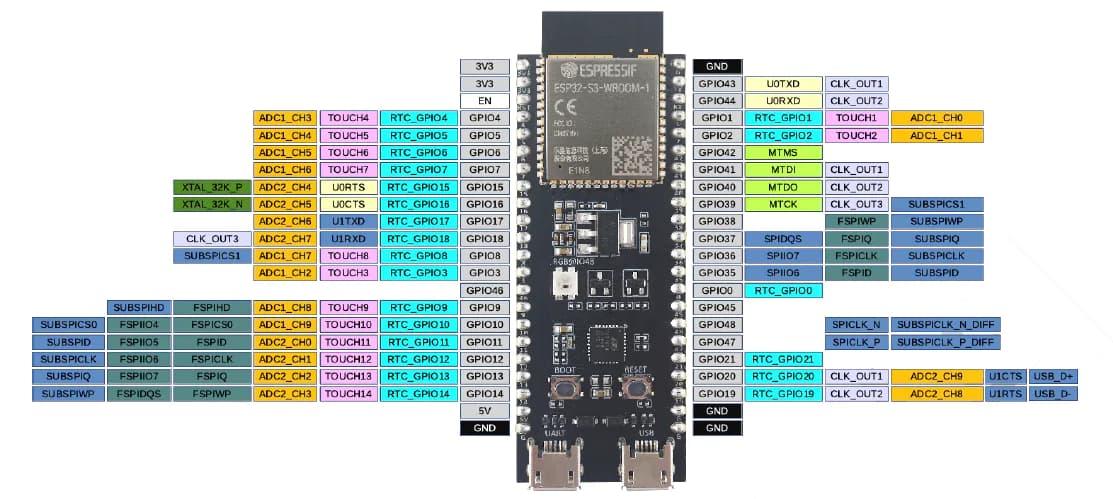
But when I use 2 DRV8302 drivers, there is a fault indicator light, below is my pin declaration code:
//motor1
#define INH_A1 4 //PWM_A
#define INH_B1 5 //PWM_B
#define INH_C1 6 //PWM_C
#define EN_GATE1 35
#define M_PWM1 3
#define M_OC1 37
#define OC_ADJ1 0
#define HALLa1 (16)
#define HALLb1 (15)
#define HALLc1 (7)
//#define pp 15 //Pole Pairs
//motor2
#define INH_A2 9 //PWM_A
#define INH_B2 10 //PWM_B
#define INH_C2 11 //PWM_C
#define EN_GATE2 13
#define M_PWM2 14
#define M_OC2 36
#define OC_ADJ2 12
#define HALLa2 (17)
#define HALLb2 (18)
#define HALLc2 (8)
You will find the dev-branch code here:
There are instructions online for how to find the library files in Arduino, and then you can replace the library with the dev-branch version.
Finding the right pins can be some work. I suggest you try one motor at a time, but with different pins… then when each motor is working alone (on different pins) combine the two setups and try them together.
Thank you, I will try
Is there any way to find the correct PID for my motor?
Start with a low P-value, I and D are both 0.
Add some code in your program to change the PID values while running the motor.
Then play with the numbers until you are happy.
I like to use @dekutree64 ´s SerialComm()
void SerialComm()
{
  switch(Serial.read())
  {
  case 'P': motor.PID_velocity.P = Serial2.parseFloat(); Serial2.print("Set ");
  case 'p': Serial2.print("motor.PID_velocity.P "); Serial2.println(motor.PID_velocity.P); break;

  case 'I': motor.PID_velocity.I = Serial2.parseFloat(); Serial2.print("Set ");
  case 'i': Serial2.print("motor.PID_velocity.I "); Serial2.println(motor.PID_velocity.I); break;

  case 'D': motor.PID_velocity.D = Serial2.parseFloat(); Serial2.print("Set ");
  case 'd': Serial2.print("motor.PID_velocity.D "); Serial2.println(motor.PID_velocity.D); break;

}

void loop{
...
...
...
   if(Serial.available() > 0){
    SerialComm();
  };
}
Thank you, I will try again, I thought there was a method to use matlab to calculate the PID number
Thank you, I have calibrated the PID and the wheel spins very smoothly.
1: Can you tell me if the FOC library can check the actual maximum speed of the engine?
2: Also, is there a way to measure engine speed without using a Hall sensor inside the wheel? Because I want to measure the speed to check if the wheel can actually rotate at that speed