Well, no, but the problem is how can the “Generic STM32F030” know which Serial port you mean? There are several USARTS, and each of them supports multiple pins. On the F030 I think it isn’t so bad, but on a high-pin count STM32F4, there could be 6 USARTS and like 40 different serial pins. But even on the F030 there are several combinations.
On a specific board, you know exactly which pins are connected to what, and hence the board definition is set up to ensure the “Serial” object just works on the expected pins.
But on a generic board, it could be any of the serial pins… how should the framework know how you set up your custom board? So it has a sensible default, presumably the first RX/TX pins of USART1, and if that isn’t right it provides #defines for you to set the ones you want. I think it’s actually a decent approach.
Unlikely. Unless you somehow burnt it, it is generally always possible to get back into the bootloader on STM32. The bootloader is built-in in the chip. The Connect under Reset procedure via SWD should still work.
I checked the datasheet of the F030C8 and it turned out exactly one pin-combo for UART1 and UART2.
But in general you are right about the pin-mapping flexibility.
For the waveshare rp2040-zero it was no problem to put the defines in the main-code. I had to select different i2c-pins.
The connect under reset didn’t work from the start. Maybe the 1k resistor between NRST and ST-link is too much?
I checked the PinMap and it includes at least two mappings for each.
That can be part of the difficulty of working with generic boards - the definitions may cover multiple chip variants and sometimes they even contain some errors… I guess STM32 doesn’t have time to test all their many chips with Arduino framework individually…
In any case that’s why you need to make things quite explicit when working with the generic board files. Set explicitly the pins you want, including alternative functions.
Well for STM32 the point of these defines is to configure the framework. So I believe you need to set them as global defines, for example in the boards config or platform config files.
Connect under reset should not even require a connection between nRST and the STLink . It’s enough to keep it low while the STLink connects, using the reset button (or a resistor like in the video).
Thanks @Candas1 and @runger . The resistor I soldered to the NRST pin lost connection.
It was only held in place by the hotglue.
With a 470R resistor I could unbrick the chip again.
I’ll try the software serial route again, but this time use a different header.
Note to myself: Never repurpose SWD pins again.
//edit I found PA2 PA3 as optional UART2 pins, but they aren’t 5V tolerant. Have to find out, where to these pins are routed on my board. Then let’s see if I can use 3.3V FTDI or CH340 adapter
While Software Serial might work ok for some basic debugging, or sending commands, you won’t be able to do motor monitoring, the performance will be too slow.
Unless you don’t have any serial pins available at all there is no reason to use software serial. If the pins for a USART are available then it’s just a matter of setting the right configuration.
I assume the problem there is that you’re not setting it for the framework files.
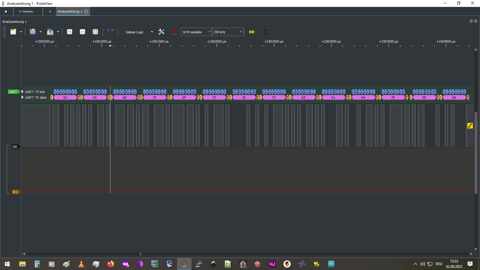
I finally got some data out of the TX-pin (HARDware Serial2 ), but I can’t see it in the Serial monitor.
Only the logicAnalyzer showed some regular packages.
I tried to translate the first package, which should be “Sensor ready”, but it only shows gibberish: (*)
When I compare the binary data of the logic analyzer with the HEX data, than they seem to be the wrong way round.
e.g. the first letter is 11001010, but the binary expression of 53HEX is 01010011
Could this be the reason why the serial monitor doesn’t work? Is there a way to switch between little endian and big endian?
I only checked the first three hex chars, but they look perfectly ok (Sen). Also the ending with 0D 0A is perfectly fine…. You seem to be sending correctly. Problems may still exist if sender and receiver expect different baud rate or start/stop bits.
RX and TX need to be crossed once, somewhere along the line. Not crossing or crossing twice are things I’ve managed to do frequently.
Setting the wrong baud rate or com port options - though usually some gibberish shows up on the terminal to clue you in that the baud rates are set differently.
Terminal connecting to some other com port (my Mac seems to have three useless ones, two of them Bluetooth related that platformio just loves to connect to instead of my MCUs
I had that in mind all the time and made sure MCU-TX was connected to FTDI-RX.
Just for fun I connected TX-TX and now it works?!
Just to clarify, I’m using a ESP8266 WEMOS-D1 module with reset pinned to GND. That way the CH340 chip acts like a USB-Serial interface for external devices.
TBH, there were several things I had wrong regarding activation of the second UART:
When you wake up UART2, you also have to use Serial2 in the pin definitions.
BTW, it works with both: MCU pin numbers and port-numbers
Now I have to figure out if the RX-pin also works by adding Commander-stuff and motor/driver definitions.
I’m a bit worried, because on MCU-RX-side is an RC-circuit with 100R resistor in line and Capacitor to GND between header and MCU.
I wonder, if they added that, because it was the long connection between the two splitboards.
One step forward, two steps back…
I tried to flash velocity control with commander and motor.monitor, but it doesn’t fit in 64k flash.
So I set target.velocity to 5 and commented out all the commander-stuff. Now it fit’s, yeah!
After powering the 40V supply up, I got some messages from serial and heard a clunk sound from the motor.
But the initialisation failed.
That was the last sign of life. For some reason the 3.3V LDO onboard only shows 0.8V.
How did I kill it? The ST-link was unplugged at that moment.
Here’s the complete code:
/*
10" hoverboard splitboard with STM32F030C8T6 MCU and hall sensors
*/
#include <SimpleFOC.h>
#define SERIAL_UART_INSTANCE    2
 #define PIN_SERIAL2_RX           PA3 //  13
 #define PIN_SERIAL2_TX           PA2 //  12
#define SIMPLEFOC_PWM_HIGHSIDE_ACTIVE_HIGH true // for Fortior FD2133S gate drivers
#define SIMPLEFOC_PWM_LOWSIDE_ACTIVE_HIGH false
BLDCMotor motor = BLDCMotor(15);
// BLDCDriver6PWM driver = BLDCDriver6PWM(A_PHASE_UH, A_PHASE_UL, A_PHASE_VH, A_PHASE_VL, A_PHASE_WH, A_PHASE_WL);
BLDCDriver6PWM driver = BLDCDriver6PWM(PA8,PB13,PA9,PB14,PA10,PB15); // blue, green, yellow gate driver pins
// Hall sensor instance
// - hallA, hallB, hallC - HallSensor A, B and C pins
// - pp - pole pairs
HallSensor sensor = HallSensor(PA0, PF1, PC15, 15); // blue, green, yellow, 15PP
// Interrupt routine intialisation
void doA(){sensor.handleA();}
void doB(){sensor.handleB();}
void doC(){sensor.handleC();}
// instantiate the commander
float target_velocity = 5;
//Commander command = Commander(Serial2);
//void doTarget(char* cmd) { command.scalar(&target_velocity, cmd); }
void setup() {
pinMode(PB9,OUTPUT); // onboard LED for heartbeat signal
// monitoring port
Serial2.begin(115200);
digitalWrite(PB9,HIGH);
// initialise encoder hardware
sensor.init();
// hardware interrupt enable
sensor.enableInterrupts(doA, doB, doC);
// link the motor to the sensor
motor.linkSensor(&sensor);
// driver config
// power supply voltage [V]
driver.voltage_power_supply = 40;
driver.init();
// link the motor and the driver
motor.linkDriver(&driver);
// aligning voltage [V]
motor.voltage_sensor_align = 6;
// set motion control loop to be used
motor.controller = MotionControlType::velocity;
// controller configuration
// default parameters in defaults.h
// velocity PI controller parameters
motor.PID_velocity.P = 0.2f;
motor.PID_velocity.I = 2;
motor.PID_velocity.D = 0;
// default voltage_power_supply
motor.voltage_limit = 20;
// jerk control using voltage voltage ramp
// default value is 300 volts per sec ~ 0.3V per millisecond
motor.PID_velocity.output_ramp = 1000;
// velocity low pass filtering time constant
motor.LPF_velocity.Tf = 0.01f;
// comment out if not needed
motor.useMonitoring(Serial2);
// initialize motor
motor.init();
// align sensor and start FOC
motor.initFOC();
// add target command T
//command.add('T', doTarget, "target voltage");
/*
Serial.println(F("Motor ready."));
Serial.println(F("Set the target velocity using serial terminal:"));
_delay(1000);
*/
}
void loop() {
motor.loopFOC();
motor.move(target_velocity);
motor.monitor();
// user communication
//command.run();
digitalWrite(PB9,LOW);
delay(100);
digitalWrite(PB9,HIGH);
}
Yeah, it fit’s in and only takes 2% more flash. I can reduce the options a lot to make it even smaller.
That should be the new commander standard for 8-biters with 64k flash mem
Hmmm… hard to say from the description what happened, but some thoughts:
don’t test with 40V until you’re confident its all correct. Usually you can get motion with a lower voltage like 10V also… I assume you’re using a PSU with current limiting? Set a low limit.
but above all, don’t test with power until you’re sure its working. You can test the driver stage by looking at the PWM signals before running the motor. Then next you can test it with power but no motor connected…
loose cables/connections. Make sure everything is soldered well, and wobbly cables are held in place by a spot of sugru, hot-glue or similar. Loose cables and connections can make it quite impossible to progress even if you got everything right. And they have potential for shorting out things they should not be touching, in the worst case this can destroy the board.
I’ve set motor.voltage_sensor_align to 6V to make sure it wouldn’t jump off the table.
Maybe that was too low?
I’m also not sure, if the place to put #define SIMPLEFOC_PWM_LOWSIDE_ACTIVE_HIGH false
in the maincode is correct? Maybe include a build_option.h file and put those compiler directives there?
In C, C++ the compiler compiles C/C++ files into object files. Each compilation unit (1 .c or .cpp file) goes through the preprocessor, where all the #defines and #includes are resolved.
The result is one massive string of c/c++ code, which the compiler turns into the object file for that c/cpp file. These different object files are then linked together in a second step, by the linker, to build the binary file loaded onto the MCU.
There may be some additional steps, but in essence this is how it works.
When you put a #define in some .c or .h file of your project, it never gets included by the .c/c++ files of the libraries or the framework. Of course not, how can they know about what’s in your project? They are supposed to be general, re-usable for all projects…
So when you want to make build-flags, i.e. #defines that affect the entire compilation, they cannot go in any .c/.cpp or .h/.hpp file of your project. They have to be defined at a global level, so they also affect the compilation of the libraries and the framework.
So you have to put them in a place where they act globally. In platformIO, this can be your platformio.ini file. In ArduinoIDE, you have to modify some framework files like the boards.cfg or platform.cfg to add the flags to some part of the configuration.
I think, I get what you’re saying, but I don’t invent these defines in my code, I overwrite them.
If I’d try to #define Rumpelstilzchen I’d get an error.
Anyway, the good news is, the board isn’t damaged. I flashed the working hall-sensor test file and it was back in the race.
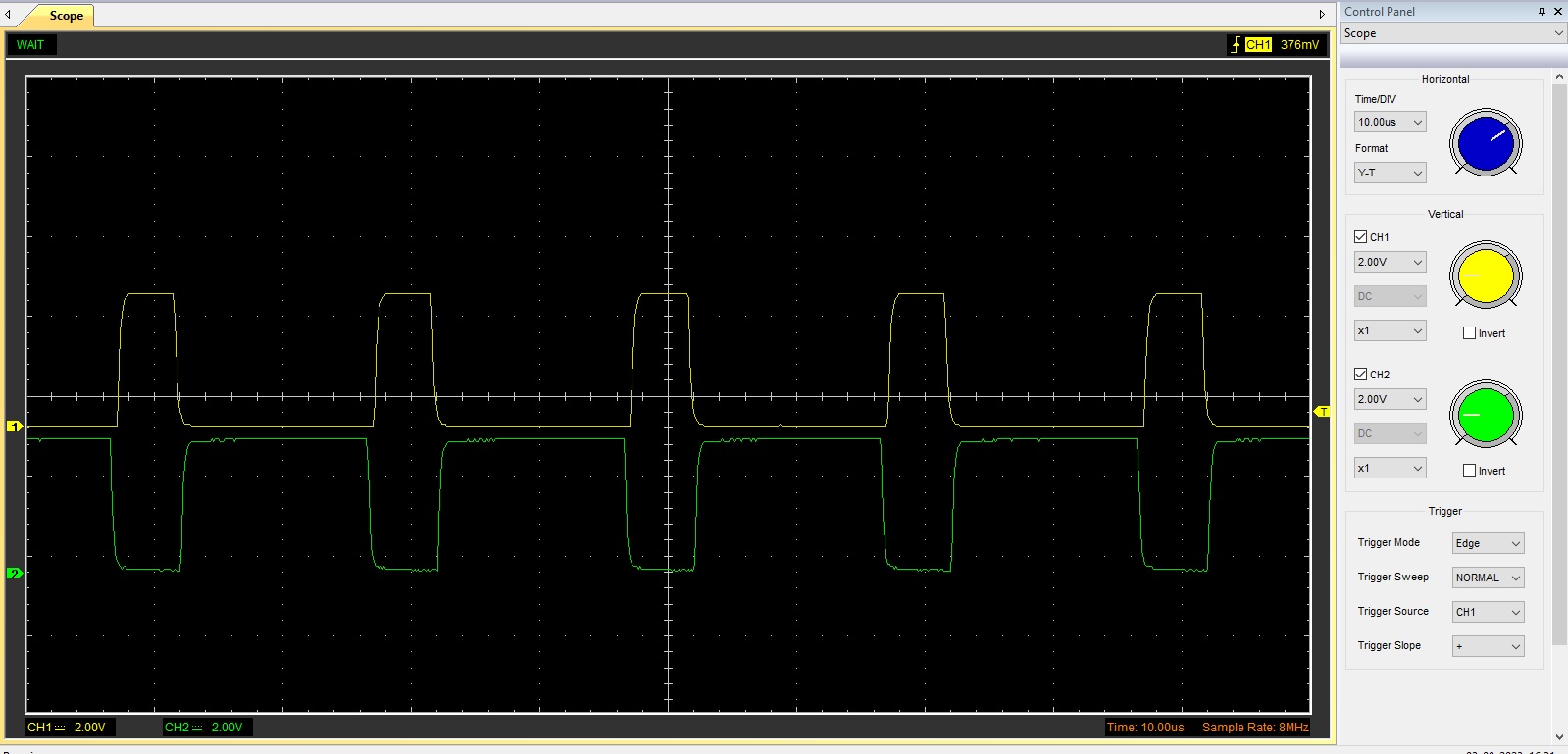
I then flashed the 6PWM driver test and could scope the H_in and L_in signals for the gate-driver.
Yellow is H_in; green is L_in