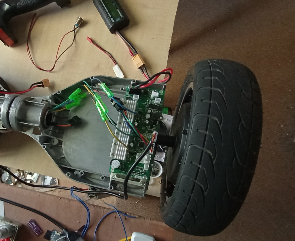
That’s my test-rig: The controller is mounted on it’s original bridge and the chassis is the aluminum part. I can only measure it with the oscilloscope. Maybe there is a general problem with ground loops? The PSU is not in the same wall-socket as the PC/Oscilloscope.
The good news is, the motor runs smooth again. The problem was the guy in front of the keyboard. ![]()
I had a delay(50) in my heartbeat-LED and also sampled the ADC of the OpAmp every loop.
I’ve thrown it all out and now I have a smooth velocity control loop of ~2kHz ![]()
Next step is to write a target_ramp function. The PSU trips everytime, I change the target too much.
Yeah the main loop timing is very sensitive.
Ideally loopfoc should run outside the main loop.
I am using a LPF but it’s not in my published code yet:
LowPassFilter LPF_target(0.5); // the higher the longer new values need to take effect
void loop()
{
…
motor.move(LPF_target(target));
Yes, a simple LPF would work, but I want a max.acceleration/deceleration function. I have to be extra careful without a current sensor.
Maybe tweak the output_ramp of the velocity control
Just for reference, I found these PID values working well for me
Setup:
- 36V, 6.5" hub motor
- voltage controlled
- velocity mode with
- smoothingSensor,
- but no currentSense:
motor.PID_velocity.P 0.20
motor.PID_velocity.I 1.00
motor.LPF_velocity.Tf 0.08
motor.PID_velocity.output_ramp 100.00
I could run the motor very slow. Above 2rad/s there were no hiccups when I changed the load to the motor. I could run it upto 102rad/s
I didn’t test LPF_velocity and PID output ramp a lot, but changing the default values in these direction improved the behavior.
//edit
Q: can I calculate the motor kV from these max-speed values? On 12V it was around 25rad/s, on 40V it’s ~100rad/s
Have you left the inductance parameter? I used it to benefit from the lag compensation.
100 rad/s seems too fast for those motors, this would mean you are doing field weakening and the kv rating will be wrong.
Here is a nice thread, at the end he explains how to check the KV rating with an oscilloscope doing the drill test.
Usually it’s around 16 RPM/V, but not all the hoverboard motors are the same, have you opened yours already to check the size of the magnets and the number of coil wires ?
Now that I have a LCR meter and an oscilloscope, I need to check the resistance/inductance and KV rating of different hoverboard motors.
I got the shaft_velocity from simpleFOCs internal calculations. Have no reason to doubt it.
I was impressed too. It was with 40V PSU, though.
The true test would be, if it reaches same speed in both directions.
I want to post another working example for the splitboard controller with the STM32F030 MCU.
The main parameters are 24V@50kHz, velocity mode with voltage-torque control.
This time I took the motor parameters from @OiD-W
I found that the PID values have a very small work-zone. A bit off and the motor runs crazy.
That’s why I added the accel2target ramp up in the main loop. It allows you to watch the motor going through the paces. Enough time to pull the plug when it gets funny
/*
  10" hoverboard splitboard with STM32F030C8T6 MCU and hall sensors
*/
#include <SimpleFOC.h>      //  has to be dev-branch for both libs
#include <SimpleFOCDrivers.h>
#include <encoders/smoothing/SmoothingSensor.h>

// Hall sensor instance
//  - hallA, hallB, hallC    - HallSensor A, B and C pins
//  - pp                     - pole pairs
HallSensor sensor = HallSensor(PA0, PF1, PC15, 15); //  blue, green, yellow, 15PP

// Interrupt routine intialisation
void doA(){sensor.handleA();}
void doB(){sensor.handleB();}
void doC(){sensor.handleC();}


BLDCMotor motor = BLDCMotor(15, 0.75, 19.0, 0.00119);  // 0.00036858); 0.75, 19, 0.00119
// BLDCDriver6PWM driver = BLDCDriver6PWM(UH, UL, VH, VL, WH, WL);
BLDCDriver6PWM driver = BLDCDriver6PWM(PA8,PB13,PA9,PB14,PA10,PB15);  //  blue, green, yellow gate driver pins

// instantiate the smoothing sensor, providing the real sensor as a constructor argument
SmoothingSensor smooth = SmoothingSensor(sensor, motor);

// instantiate the commander
float target_velocity = 0;
float accel2target = 0;
bool LED = true;
void SerialComm()
{
  switch(Serial2.read())
  {
  case '?':
    Serial2.print("sensor_direction ");
    Serial2.print(motor.sensor_direction);
    Serial2.print(", zero_electric_angle ");
    Serial2.println(motor.zero_electric_angle);
    break;
  case 's': Serial2.print("shaft_velocity "); Serial2.println(motor.shaft_velocity); break;
  case 'a':
    Serial2.print("shaft_angle ");
    Serial2.print(motor.shaft_angle);
    Serial2.print(", electric_rotations ");
    Serial2.print(sensor.electric_rotations);
    Serial2.print(", electric_sector ");
    Serial2.println(sensor.electric_sector);
    break;

  case 'T': target_velocity = Serial2.parseFloat(); Serial2.print("Set ");
  case 't': Serial2.print("target "); Serial2.println(target_velocity);  break;

  case 'V': motor.voltage_limit = Serial2.parseFloat(); Serial2.print("Set ");
  case 'v': Serial2.print("motor.voltage_limit "); Serial2.println(motor.voltage_limit); break;

  case 'O': motor.PID_velocity.output_ramp = Serial2.parseFloat(); Serial2.print("Set ");
  case 'o': Serial2.print("motor.PID_velocity.output_ramp "); Serial2.println(motor.PID_velocity.output_ramp); break;

  case 'F': motor.LPF_velocity.Tf = Serial2.parseFloat(); Serial2.print("Set ");
  case 'f': Serial2.print("motor.LPF_velocity.Tf "); Serial2.println(motor.LPF_velocity.Tf); break;
  case 'P': motor.PID_velocity.P = Serial2.parseFloat(); Serial2.print("Set ");
  case 'p': Serial2.print("motor.PID_velocity.P "); Serial2.println(motor.PID_velocity.P); break;
  case 'I': motor.PID_velocity.I = Serial2.parseFloat(); Serial2.print("Set ");
  case 'i': Serial2.print("motor.PID_velocity.I "); Serial2.println(motor.PID_velocity.I); break;
  case 'D': motor.PID_velocity.D = Serial2.parseFloat(); Serial2.print("Set ");
  case 'd': Serial2.print("motor.PID_velocity.D "); Serial2.println(motor.PID_velocity.D); break;

  case 'W': motor.P_angle.P = Serial2.parseFloat(); Serial2.print("Set ");
  case 'w': Serial2.print("motor.P_angle.P "); Serial2.println(motor.P_angle.P); break;

// motor.zero_electric_angle
  case 'Z': motor.zero_electric_angle = Serial2.parseFloat(); Serial2.print("Set ");
  case 'z': Serial2.print("motor.zero_electric_angle "); Serial2.println(motor.zero_electric_angle); break;

  case ' ': target_velocity = 0; motor.voltage_limit = 0;
  }
}

void setup() {
  pinMode(PB9,OUTPUT);  //  onboard LED for heartbeat signal

// monitoring port
  Serial2.begin(115200);
  while(!Serial2){};

  digitalWrite(PB9,LED);

  // initialise encoder hardware
  sensor.init();
  // hardware interrupt enable
  sensor.enableInterrupts(doA, doB, doC);

  // set SmoothingSensor phase correction for hall sensors
  //smooth.phase_correction = -_PI_6;
  motor.linkSensor(&smooth); // link the motor to the smoothing sensor

  // driver config
  // power supply voltage [V]
  driver.pwm_frequency = 50000;
  driver.voltage_power_supply =24;
  driver.voltage_limit = 24;
  driver.dead_zone = 0.1f;  // default 0.05f
  driver.init();
  // link the motor and the driver
  motor.linkDriver(&driver);

  // aligning voltage [V]
  motor.voltage_sensor_align = 6;

// set motion control loop to be used
  motor.torque_controller     = TorqueControlType::voltage;
  // motor.foc_modulation = FOCModulationType::Trapezoid_120;
  motor.foc_modulation        = FOCModulationType::SinePWM;
  // motor.controller     = MotionControlType::torque;    // set motion control loop to be used
  motor.controller     = MotionControlType::velocity;


  // controller configuration
  // default parameters in defaults.h

  // velocity low pass filtering time constant
  motor.PID_velocity.P  = 0.3f;
  motor.PID_velocity.I  = 0.3f;
  motor.LPF_velocity.Tf = 0.04f;  //  0.05

  // default voltage_power_supply
  motor.voltage_limit = 0.5f * driver.voltage_limit;
  motor.current_limit = 10;
  // jerk control using voltage voltage ramp
  // default value is 300 volts per sec  ~ 0.3V per millisecond
  motor.PID_velocity.output_ramp = 1000;

  // comment out if not needed
 motor.useMonitoring(Serial2);

  // initialize motor
  motor.init();
  // align sensor and start FOC
  motor.zero_electric_angle  = 0.00f; // rad
  motor.sensor_direction = Direction::CCW; // CW or CCW
  motor.initFOC();

  _delay(1000);

 }

void loop() {
  digitalWrite(PB9,LED);
  if (LED == true){
	  LED = false;}
	else {LED = true;}

  motor.loopFOC();
  //motor.monitor();
  motor.move(accel2target);
  // user communication
  if(Serial2.available() > 0){
    SerialComm();
  };
  if (target_velocity != accel2target){
    if (target_velocity < accel2target) {accel2target -= 0.01f;}
    else {accel2target += 0.01f;}
  }
  //Serial2.println(motor.shaft_velocity);
}
Isn’t 50Khz too much ?
Too much for the big FETs?
I tested it also with 32kHz. Then the P and I values are 0.2
I’m not done testing. The dead-time is still to high and I have a bit of oscillation in the velocity
// set SmoothingSensor phase correction for hall sensors
  //smooth.phase_correction = -_PI_6;
I borrowed that line from you, but never tried it.
Do you still use it?
Sorry I missed this answer.
I use those motors at 16Khz. We are too old to hear the different going higher.
I don’t see the benefit.
No wonder why you motors are spinning so fast, if you don’t use this with sensor smoothing in combination with hall sensors, you are doing field weakening.
That’s also why your KV is wrong.
I tried it with phase correction and it was quieter under load. But I still can reach the same topspeed of ~55 rad/s on 24V. I noticed the noLoad current was lower, too.
So it’s a win_win_win situation for me.
I stick with 32KHz then, my cat has ears, too ![]()
I measured the kV long before I used phase_resistance, kV, Inductance.
It was plain voltage control set to 1V and read the shaft_velocity.
I can’t make any comments on the motor inductance. Did you find the time to use your new LCR-meter?
It would be cool to have a L_kV_R database for common motors ( gimbal and hub motors)
No I am trying to do too many things in parallel. I should stop and use it.
But I must say the 0.00036858H I found somewhere on internet worked well for me.
At a given speed, increasing or reducing the phase inductance would increase the consumption.
And the lag compensation in voltage mode works surprisingly better for me than FOC.
I suspect the delay in FOC calculation is impacting the efficiency.
I need to:
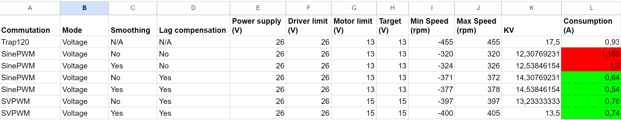
- make sure the phase currents are balanced, by tweaking the gains until the amplitude is same for both waveforms. This probably happens on hoverboard controllers because we use the mosfets as shunts. This can be additional work for the PI controller. This is a test I did on a gsheet

- I need to tweak the PI controller better

Then I will could test if my assumptions are correct by adding delay in loopfoc and see if it increases the consumption
I worry about cats and BLDC noise too ![]() But they can hear 64KHz, so 32 might just make it worse. 15 is hideous to my ears, so I use 25 to be sure it’s well outside human range. 8 is merely annoying, so hopefully 25 for a cat sounds similar and not painful. Though it is getting toward the upper end for dogs.
But they can hear 64KHz, so 32 might just make it worse. 15 is hideous to my ears, so I use 25 to be sure it’s well outside human range. 8 is merely annoying, so hopefully 25 for a cat sounds similar and not painful. Though it is getting toward the upper end for dogs.
I have a deaf cat ![]()
But another cat and a dog also.
I think they are more worried about the motor jumping on my table in the living room.
So far my cat stays cool when I test motors. But he panicced when I stepped on the hoverboard and drove circles around the livingroom table ![]()
I tried to get readings from the MP6050 on my splitboard.
I tried the “tinyMP6050” library, but i couldn’t get any data.
Furthermore, it uses 51% of my flash! Tiny?? My A$$…
I wonder, how the hoverboard FW was able to use the IMU and also control the motor, LEDs, blutooth…
This would also benefit from Qfplib
I used it in the past precisely because I had no space left on a gd32f130c6t6.
Replacing trig functions helped.
And this tiny library is not even using the DMP… DMP makes it much worse.